

Biomass raw material processing device in field of new energy
A biomass raw material and processing device technology, which is applied in grain processing, cutting equipment, agricultural machinery and implements, etc., can solve the problems of different sizes of straws, repeated rework, and the crushed particles cannot meet the requirements for use. Good effect, improve efficiency, prevent clogging
- Summary
- Abstract
- Description
- Claims
- Application Information
AI Technical Summary
Problems solved by technology
Method used
Image

Examples
specific Embodiment approach 1
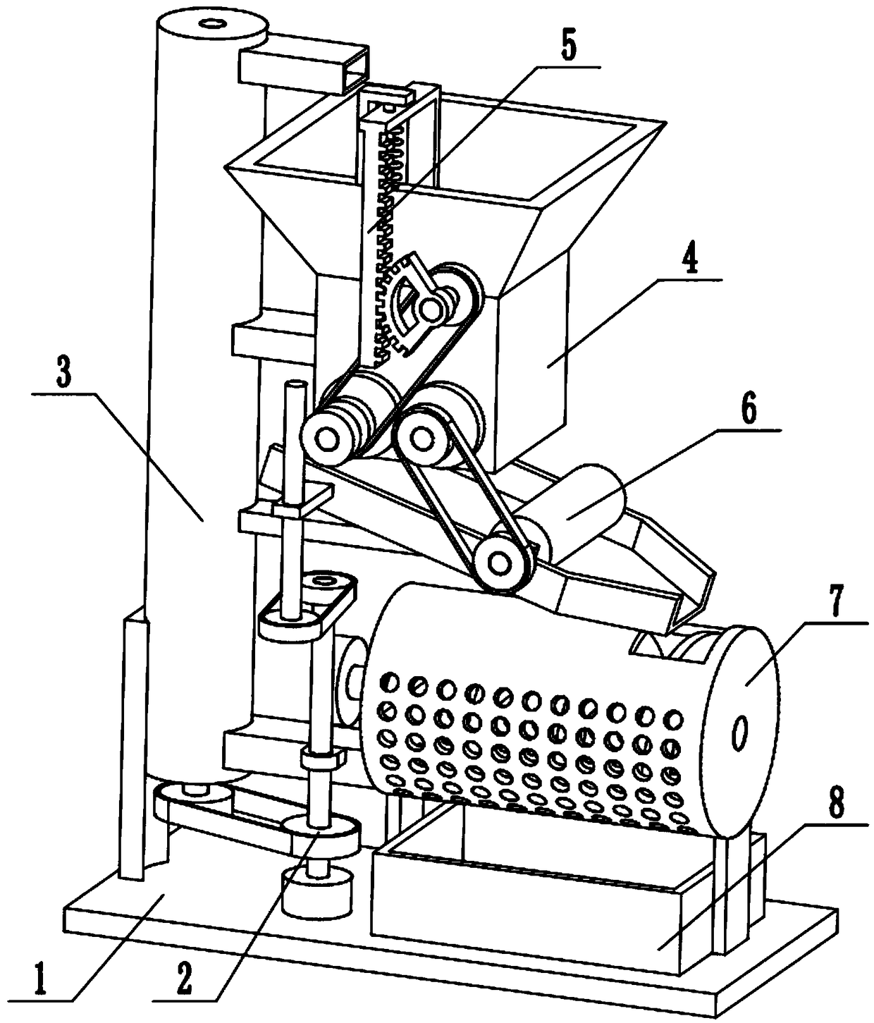
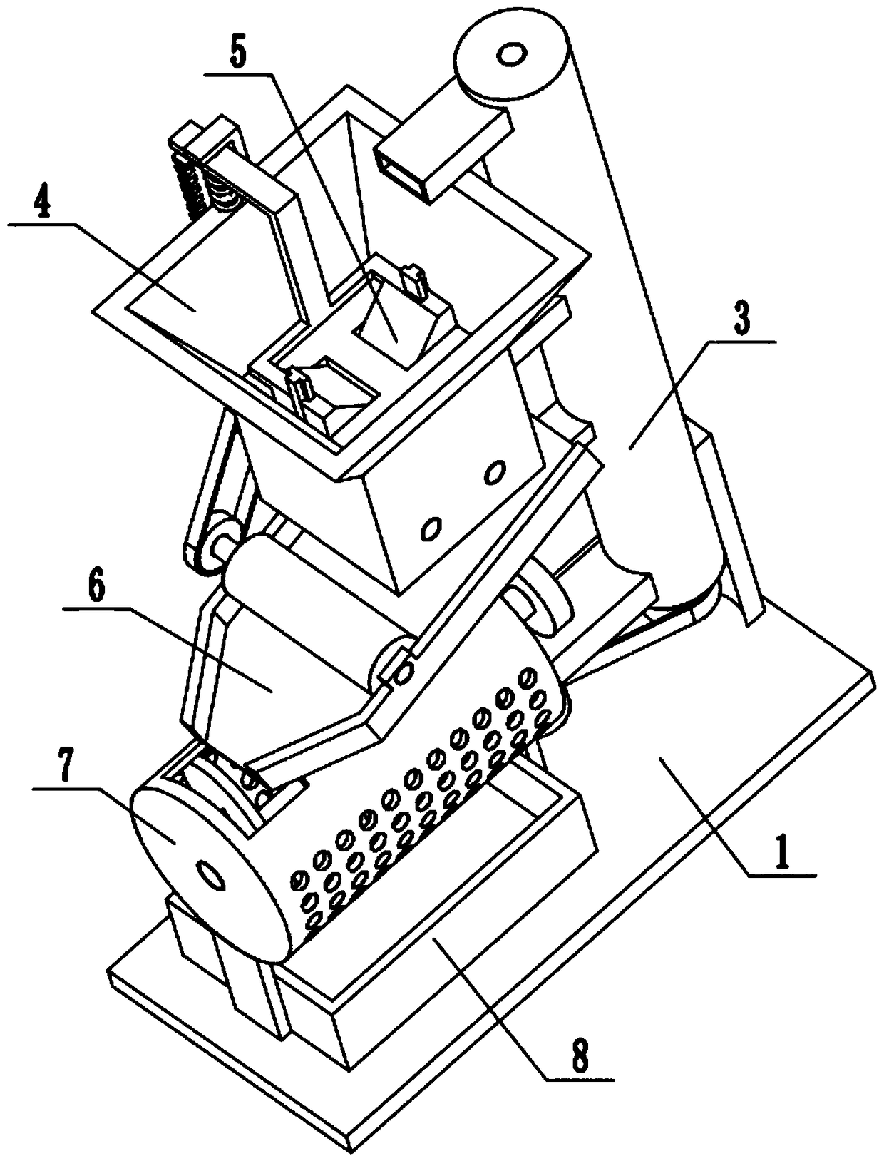
[0025] Combine below Figure 1-8Describe this embodiment, a biomass raw material processing device in the field of new energy, including a base 1, a power mechanism 2, a circulation assembly 3, a crushing assembly 4, an intermittent feeding assembly 5, a material guide plate 6, a screening assembly 7 and The collection box 8, the power mechanism 2 is fixedly connected to the middle end of the base 1, the power mechanism 2 is connected to the looping assembly 3 through a belt transmission, the looping assembly 3 is fixedly connected to the left end of the base 1, and the crushing assembly 4 is fixedly connected to the The upper end of the loop back assembly 3, the power mechanism 2 is meshed with the crushing assembly 4, and the intermittent feeding assembly 5 is slidably connected in the crushing assembly 4, and the intermittent feeding assembly 5 is connected with the crushing assembly 4, and the material guide plate 6 is fixedly connected. At the middle end of the circulatin...
specific Embodiment approach 2
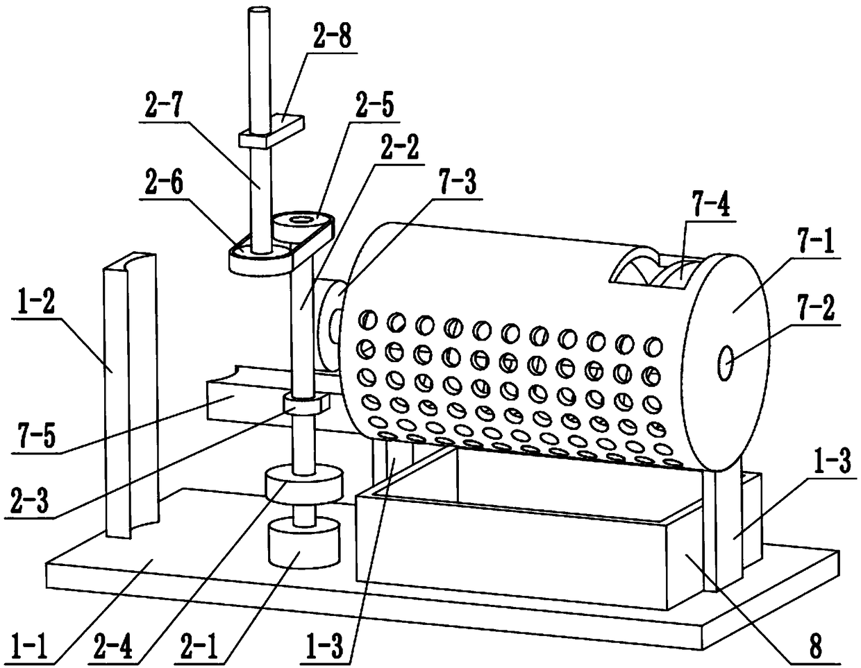
[0026] Combine below Figure 1-8 To illustrate this embodiment, the base 1 includes a bottom plate 1-1, a support plate 1-2, and a side frame plate 1-3; the support plate 1-2 is fixedly connected to the left end of the bottom plate 1-1, and the loopback assembly 3 is fixedly connected On the support plate 1-2, two side frame plates 1-3 are fixedly connected to the right end of the bottom plate 1-1, and the collection box 8 is located between the two side frame plates 1-3.
specific Embodiment approach 3
[0027] Combine below Figure 1-8 To illustrate this embodiment, the power mechanism 2 includes a motor 2-1, a worm I2-2, a shaft frame plate 2-3, a driving pulley I2-4, a driving pulley II2-5, and a driven pulley II2-6 , worm II 2-7 and horizontal plate 2-8; the motor 2-1 is fixedly connected to the middle end of the bottom plate 1-1, the output shaft of the motor 2-1 is connected with the worm I 2-2 through a coupling, and the driving pulley I 2- 4 and driving pulley II 2-5 are respectively fixedly connected to both ends of the worm I 2-2, the middle end of the worm I 2-2 is rotatably connected to the shaft frame plate 2-3 through a bearing with a seat, and the shaft frame plate 2-3 is fixedly connected On the screening assembly 7, the driving pulley Ⅰ2-4 is connected with the circulation return assembly 3 through a belt transmission, the driving pulley Ⅱ2-5 is connected with the driven pulley Ⅱ2-6 through a belt transmission, and the driven pulley Ⅱ2-6 It is fixedly connect...
PUM
 Abstract
Description
Claims
Application Information