Positioning chaplet for casting, application process thereof and combined core

A positioning core and core support technology, which is applied in core support, combined core, positioning core support for casting and its application process, can solve the problems of poor positioning effect and complex structure, achieve good positioning effect, reduce operation difficulty, Avoid shaking effects

Pending Publication Date: 2019-02-01
DONGFENG COMML VEHICLE CO LTD
View PDF12 Cites 7 Cited by
  • Summary
  • Abstract
  • Description
  • Claims
  • Application Information

AI Technical Summary

Problems solved by technology

[0008] The purpose of the present invention is to overcome the defects and problems of complex structure and poor positioning effect in the prior art, and provide a positioning core support with simple structure and good positioning effect, its application process, and the combined core

Method used


Image

  • Positioning chaplet for casting, application process thereof and combined core
  • Positioning chaplet for casting, application process thereof and combined core
  • Positioning chaplet for casting, application process thereof and combined core

Examples


Embodiment 1

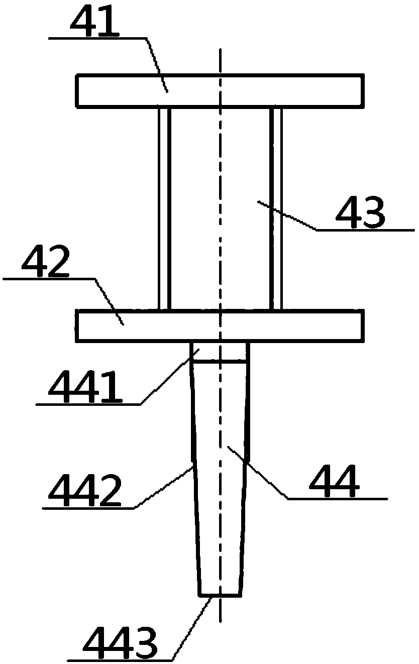
[0059] see Figure 1 to Figure 7 , a positioning core support for casting, including an upper support 41 and a lower support 42, the upper support 41 and the lower support 42 are flat plate structures, and the upper support 41 and the lower support 42 are parallel to each other; The core support 4 also includes a connecting rod 43 and a positioning pin 44, the bottom surface of the upper support 41 is vertically connected with the top of the connecting rod 43, the bottom of the connecting rod 43 is vertically connected with the top surface of the lower support 42, and the lower support The bottom surface of seat 42 is vertically connected with the top of locating pin 44, and the bottom of locating pin 44 extends downwards; Arranged in order below. Preferably, the positioning pin 44 includes a top pin surface 441, a middle pin portion 442 and a bottom pin surface 443. The top end is vertically connected, the bottom end of the middle pin portion 442 is vertically connected wit...

Embodiment 2

[0065] Basic content is the same as embodiment 1, the difference is:

[0066] The sum of the thicknesses of the upper support 41 and the lower support 42 is less than or equal to the diameter of the connecting rod 43, the thickness of the upper support 41 and the lower support 42 is greater than or equal to 1.5 mm, and the diameter of the connecting rod 43 is greater than or equal to equal to 3 millimeters. The side wall of the connecting rod 43 is provided with a coarse thread 5 .

Embodiment 3

[0068] Basic content is the same as embodiment 1, the difference is:

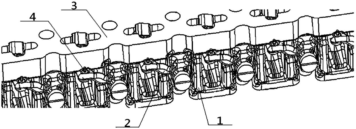
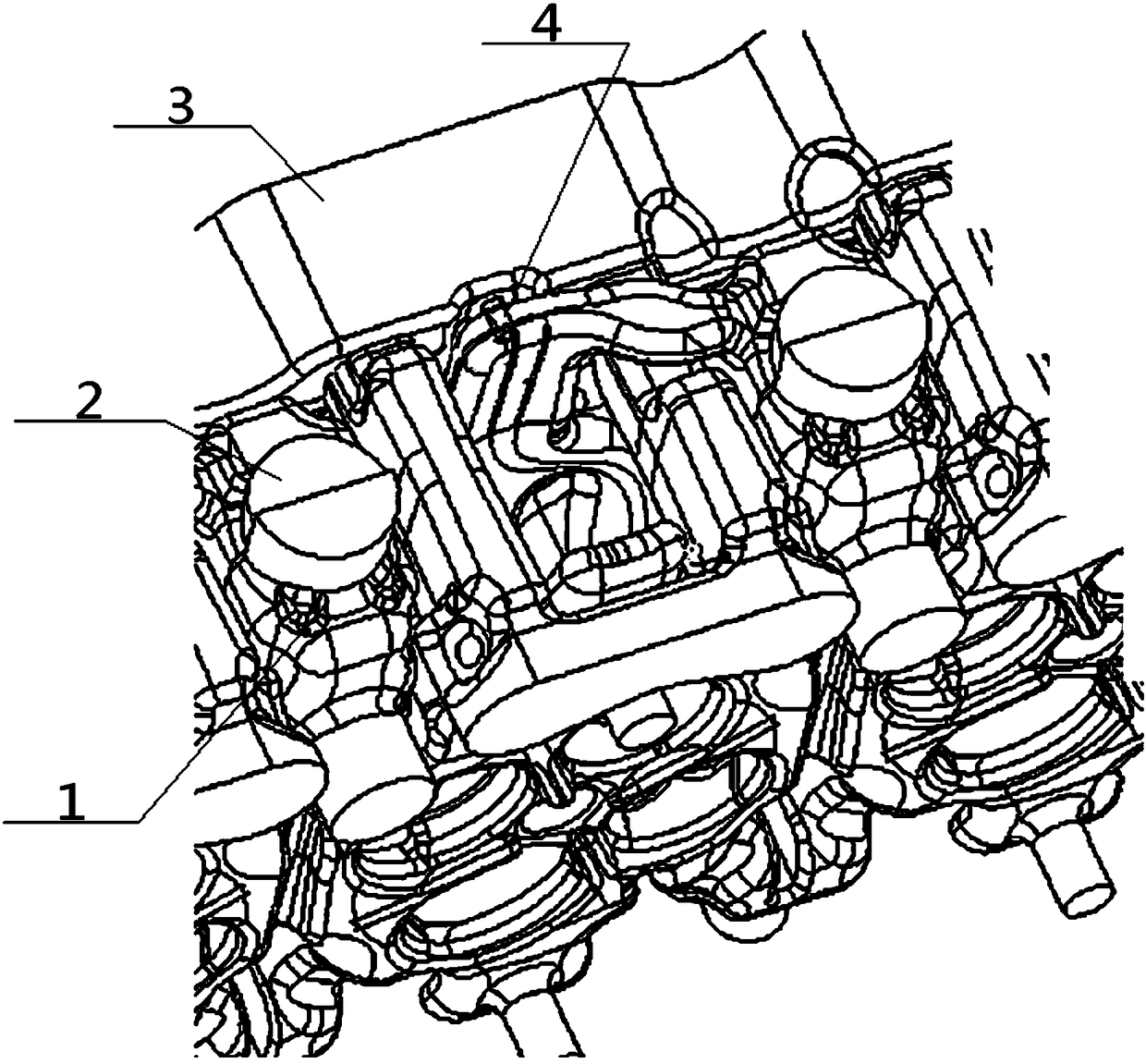
[0069] The upper water jacket core 2 is provided with a plurality of positioning grooves 22, and the bottom of the positioning grooves 22 is provided with a lower positioning hole 21 to be inserted and matched with the positioning pin 44, and the lower support 42 is embedded in the positioning groove 22. internal. The positioning groove 22 is opened at the heat node 6 on the upper water jacket core 2 .


PUM


Abstract

The invention provides a positioning chaplet for casting. The positioning chaplet comprises an upper supporting seat, a connecting rod, a lower supporting seat and a positioning pin which are sequentially connected from top to bottom, wherein the connecting rod is provided with rough threads, a combined core where the chaplet is located comprises an oil tank core, upper water jacket cores and lower water jacket cores which are sequentially arranged from top to bottom, a plurality of chaplet bodies are arranged between the oil tank core and the upper water jacket cores, a plurality of upper supporting points are arranged on the bottom surface of the oil tank core so as to be in supporting fit with the upper supporting seat in the chaplet, a plurality of lower positioning holes are formed inthe upper water jacket cores so as to be inserted and matched with the positioning pin, and the positions of the lower positioning holes are preferably selected as the positions of hot joints in theupper water jacket cores. According to the design, the structure is simple, the positioning effect is good, the heat joint distribution can be reduced, and the shrinkage defect can be eliminated.

Description

technical field [0001] The invention relates to a core support, which belongs to the field of casting, in particular to a positioning core support for casting and its application process, and the combined core, which is specifically suitable for simplifying the structure, improving the positioning effect, reducing the distribution of hot spots, and eliminating shrinkage defects . Background technique [0002] Existing engine cylinder heads are mostly manufactured by casting. During the production process, sand cores need to be placed in the sand box for core assembly, and then molten iron is injected to fill the mold to complete the casting. During the process, it is necessary to Use corbels. [0003] The application publication number is CN105215294A, and the application publication date is January 6, 2016. The invention patent application discloses a core support, which includes a core column, a pair of bases and connectors. The core column includes oppositely arranged fi...

Claims


Application Information

Patent Timeline
Patent Type & Authority Applications(China)
IPC IPC(8): B22C21/14B22C9/10
CPCB22C9/103B22C9/108B22C21/14
Inventor 涂欣达唐民峰张士斌
Owner DONGFENG COMML VEHICLE CO LTD
Why Eureka
Try Eureka