
Voltage detecting circuit, battery power prompting system and voltage detecting method

A voltage detection circuit and circuit technology, applied in the direction of using digital measurement technology for measurement, measurement device, measurement of electrical variables, etc., can solve the problem that the pins of digital chips can no longer meet the requirements, increase the system volume and cost, and the pins hinder the digital Chip expansion and other issues, to achieve the effect of being conducive to system integration, reducing leakage probability, and reducing complexity

Pending Publication Date: 2019-02-01
HANGZHOU BOON ELECTRONICS CO LTD
View PDF0 Cites 0 Cited by
  • Summary
  • Abstract
  • Description
  • Claims
  • Application Information

AI Technical Summary

Problems solved by technology

When the detection accuracy requirements increase, the pins of the digital chip can no longer even meet the requirements
Moreover, occupying too many pins also hinders the expansion of other functions of the digital chip.
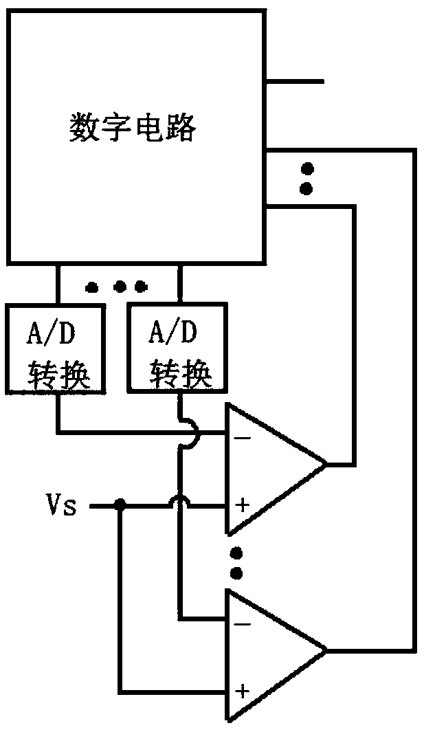
In addition, this solution additionally uses multiple A / D converters and multiple comparators, which greatly increases the size and cost of the system

Method used


Image

  • Voltage detecting circuit, battery power prompting system and voltage detecting method
  • Voltage detecting circuit, battery power prompting system and voltage detecting method
  • Voltage detecting circuit, battery power prompting system and voltage detecting method

Examples


Embodiment Construction

[0038] In order to further understand the present invention, the preferred embodiments of the present invention are described below in conjunction with examples, but it should be understood that these descriptions are only to further illustrate the features and advantages of the present invention, rather than limiting the claims of the present invention.

[0039] The description in this part is only for several typical embodiments, and the present invention is not limited to the scope of the description of the embodiments. The mutual replacement of the same or similar prior art means and some technical features in the embodiments is also within the scope of the description and protection of the present invention.

[0040] "Coupling" in the specification includes direct connection and indirect connection, such as connection through an electrically conductive medium such as a conductor, wherein the electrically conductive medium may contain parasitic inductance or parasitic capac...


PUM


Abstract

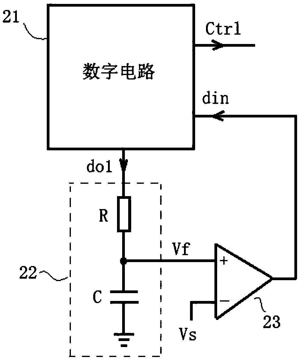
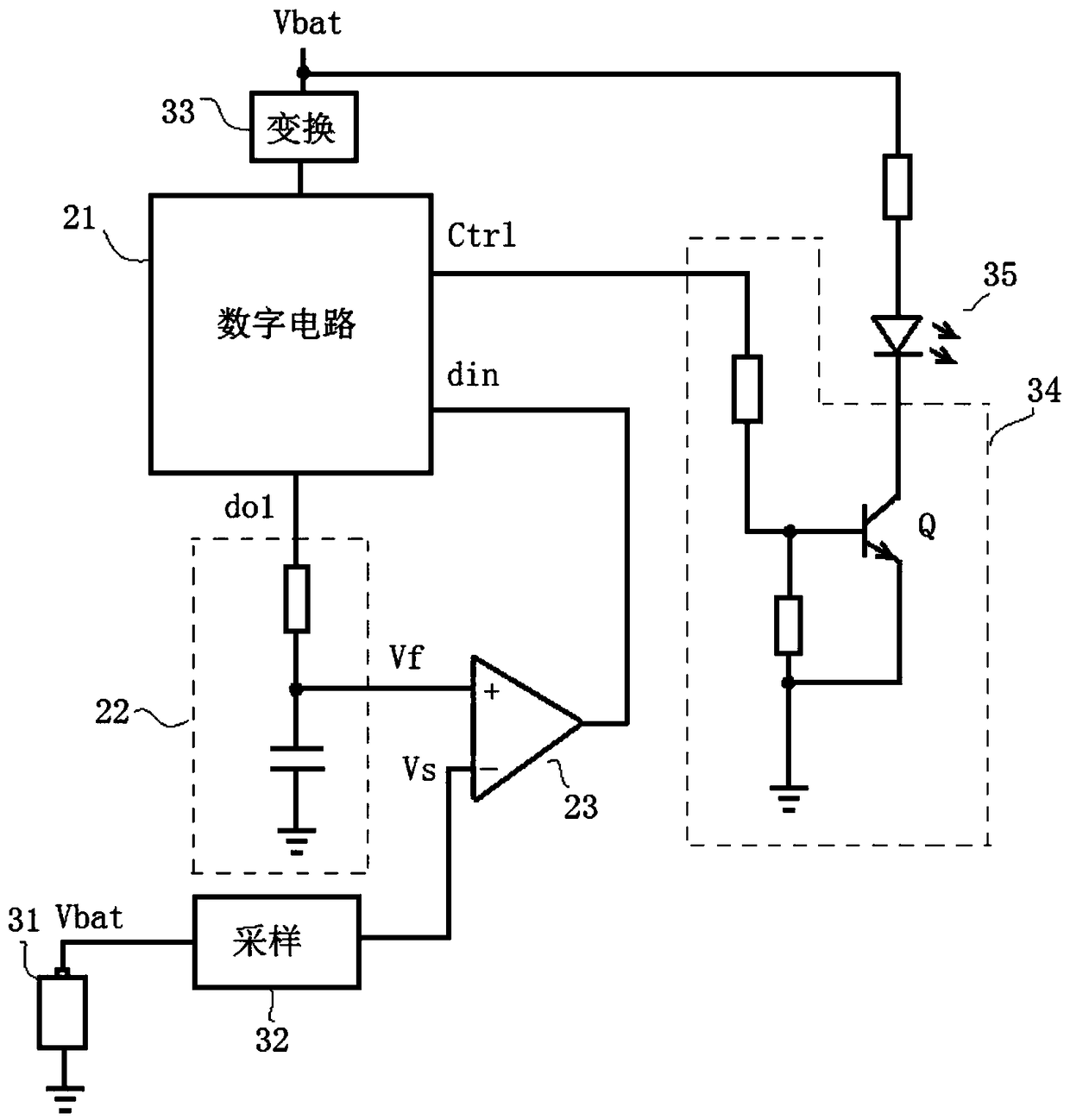
The invention provides a voltage detecting circuit, a battery power prompting system and a voltage detecting method. The voltage detecting circuit based on a digital circuit comprises a digital circuit, a conversion circuit and a comparison circuit. The digital circuit has a first output end, an input end and a second output end. The first output end outputs a digital signal. The input end of theconversion circuit is coupled to the first output end of the digital circuit. The first input end of the comparison circuit receives a voltage signal representative of the to-be-detected voltage. Thesecond input end of the comparison circuit is coupled to the output end of the conversion circuit. The output end of the comparison circuit is coupled to the input end of the digital circuit. The digital circuit obtains a to-be-detected voltage level based on the output signal of the comparison circuit, and provides a control signal at the second output end of the digital circuit, wherein the control signal is generated based on the to-be-detected voltage level. According to the voltage detecting circuit, the battery power prompting system and the voltage detecting method in the embodiment, the detection can be realized only by occupying two pins of the digital circuit, so that extension of other functions of the digital circuit is facilitated; meanwhile, the complexity, the volume and thecost of the system are reduced, so that the system integration is facilitated, thereby improving the reliability of a portable electric tool in a relatively poor working environment.

Description

technical field [0001] The invention relates to an electronic circuit, in particular to a voltage detection circuit, a battery power prompt system and a voltage detection method. Background technique [0002] For electric tools, because there may be no mains power supply in some workplaces, or the use of power cords may cause inconvenience to work, so portable electric tools with built-in batteries have greater advantages. However, a sudden lack of battery power can cause problems for work. Therefore, an indication of the battery power level is also crucial to facilitate timely charging and prevent sudden power failure. [0003] In the circuit control of a portable electric tool, in order to reduce the research and development cost and facilitate the expansion of control functions, a digital chip is used. figure 1 A digital chip-based battery power detection scheme in a comparative technology is shown. In this scheme, the digital circuit outputs multiple digital signals i...

Claims


Application Information

Patent Timeline
Patent Type & Authority Applications(China)
IPC IPC(8): G01R31/3835G01R19/25
CPCG01R19/2503
Inventor 王海
Owner HANGZHOU BOON ELECTRONICS CO LTD
Learn More