Split type metal reflector with flexible mounting structure and angle adaptive adjustment method

A technology for metal mirrors and mounting structures, applied in installation, optics, instruments, etc., can solve the problems of difficulty in simultaneously ensuring the angle adjustment of metal mirrors, surface shape accuracy requirements, reducing mirror processing costs and angle adjustment, etc., to achieve simplification Angle adjustment link, easy processing and assembly, high connection rigidity effect

Inactive Publication Date: 2019-02-01
LUOYANG INST OF ELECTRO OPTICAL EQUIP OF AVIC
4 Cites 8 Cited by

AI-Extracted Technical Summary

Problems solved by technology

[0007] In order to solve the problem that the existing integrated metal mirror support structure is difficult to simultaneously ensure the angle adjustment of the me...

Method used

In above-mentioned technical scheme, can require according to different environmental conditions, be selected in different flexible structural materials and flexible structural form, realize the best destressing effect by adjusting the flexibility of flexible structure, principle is to meet environmental conditions Under the premise of improving the flexibility as much as possible, reducing the difficulty of processing and assembling the reflector and flexible structure.
[0027] The metal reflector separates the mounting structure from the mirror body, and ado...

Abstract

The invention relates to a split type metal reflector with flexible mounting structure and an angle adaptive adjustment method, and belongs to the technical field of high precision optical component flexible support level adjusting mechanism. The split type metal reflector with flexible mounting structure comprises two parts of a reflector body and a flexible mounting structure for adjusting the angle, the metal reflector and the flexible mounting structure adopt a three-point side rigid connection mode. The flexible load cell groove design is adopted at the connecting structure of the metal reflector body, and used to solve the installation stress problem caused by the adjustment of the isolation angle and the unevenness of the mounting surface; and three identical flexible mounting structures are arranged on the two sides of the short axis of the rectangular reflector body, so as to realize the angle adjustment of minor axis direction of reflector body and the adaptive adjustment forangle of long axis direction, and reduces the influence of the angle adjustment on the reflector surface type. The reflector mounting structure of the invention can be applied to the metal folding reflector of the medium-long wave infrared light system, and other occasions which are higher for reflector surface shape and angle adjustment requirements.

Application Domain

Mountings

Technology Topic

Self adaptiveType metal +7

Image

  • Split type metal reflector with flexible mounting structure and angle adaptive adjustment method
  • Split type metal reflector with flexible mounting structure and angle adaptive adjustment method
  • Split type metal reflector with flexible mounting structure and angle adaptive adjustment method

Examples

  • Experimental program(1)

Example Embodiment

[0025] The present invention will now be further described in conjunction with the embodiments and accompanying drawings:
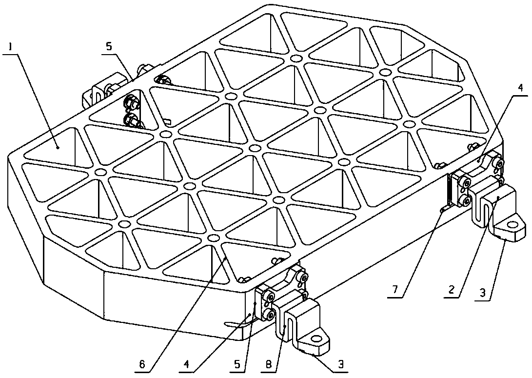
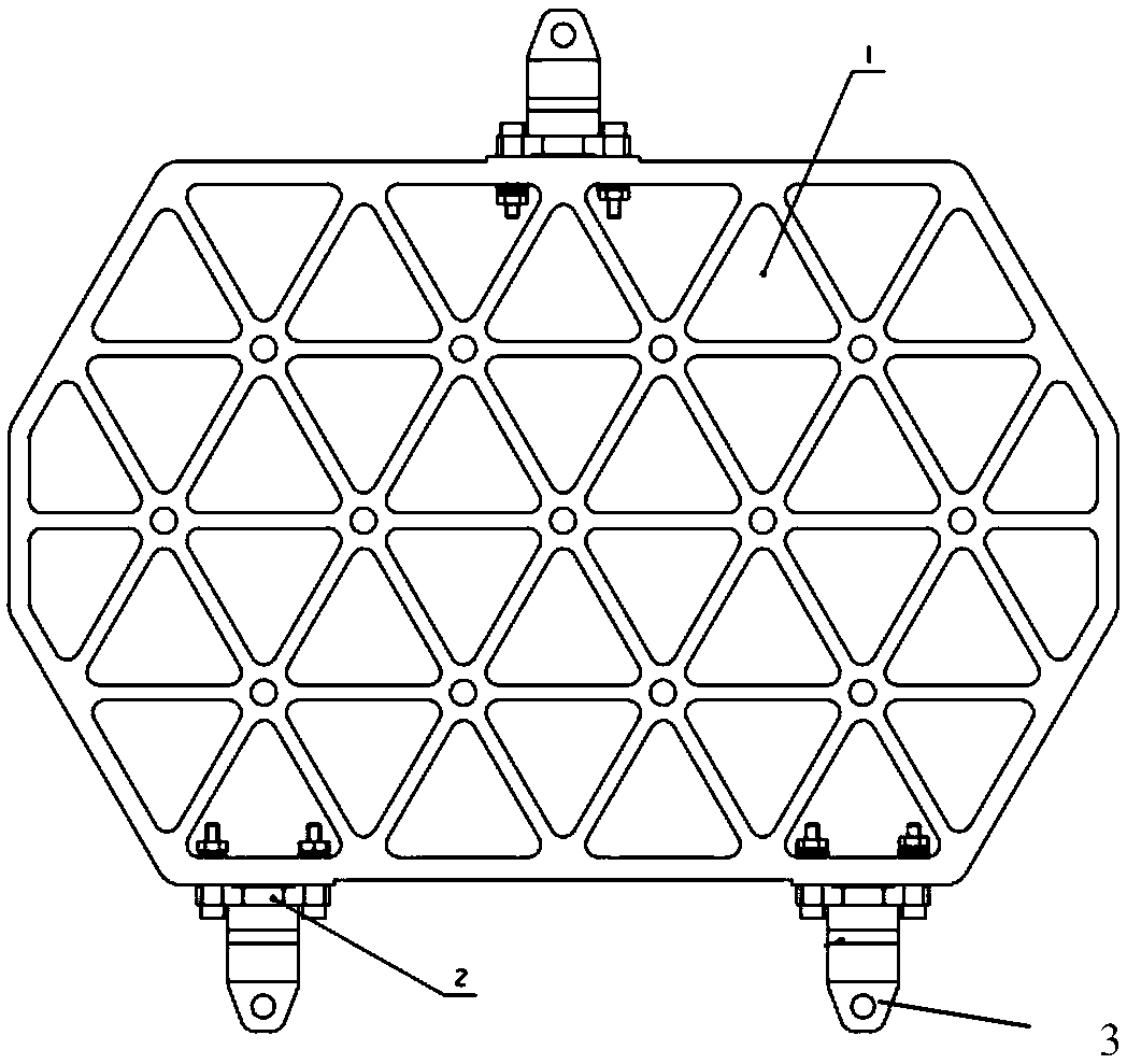
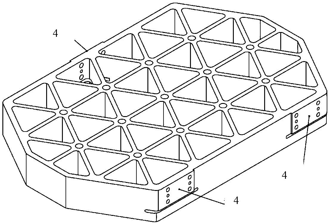
[0026] The invention provides a flexible installation structure of a metal mirror with self-adaptive angle adjustment, including a metal mirror and a flexible installation structure, the flexible installation structure has the characteristics of angle adjustment and flexible structure, and realizes the compensation function of angle adjustment and installation stress. When performing the angle adjustment in the direction of the long axis of the mirror, it is not necessary to carry out the angle research of the relevant installation surface, and it is only realized by the relative rotation of the metal mirror and the installation surface of the flexible installation structure, which will not bring additional installation stress. , and the process is simple.
[0027] The metal reflector separates the mounting structure from the mirror body, and adopts a triangular reinforcing rib on the back. In addition, in order to reduce the influence of mounting stress on the shape of the reflector, an unloading groove is designed between the mounting structure and the mirror. The three flexible mounting structures form an equilateral triangle and are distributed on both sides of the metal reflector using triangular reinforcing ribs. Each flexible mounting structure is designed with a corresponding flexible structure to reduce the influence of the mounting surface stress on the reflector surface.
[0028] In the above technical solution, since each mounting surface of the connection structure has good workability, the precision should be improved as much as possible to reduce the influence of mounting stress on the mirror surface type, and to improve the consistency and assembly efficiency during mass assembly.
[0029] In the above technical solution, different flexible structural materials and flexible structural forms can be selected according to different environmental conditions, and the best stress relief effect can be achieved by adjusting the flexibility of the flexible structure. The principle is to meet the environmental conditions. , try to improve the flexibility and reduce the difficulty of processing and assembling the mirror and flexible structure.
[0030] In the above technical solution, a certain gap is reserved between the metal reflector and the connection hole of the flexible mounting structure, and angle adjustment in different ranges can be realized by appropriately adjusting the maximum gap and spacing of the mounting hole.
[0031] In the above technical solution, corresponding pin bottom holes are reserved in corresponding positions on the metal reflector and the flexible mounting structure, and after the reflector is adjusted in place, it is fixedly connected by fasteners and pins.
[0032] like Figure 1-4 As shown in the figure, the flexible installation structure for adaptive angle adjustment of the present invention includes a metal reflection mirror 1 and a sub-flexible installation structure 2, and the metal reflection mirror 1 and the flexible installation structure 2 are connected and fixed by bolts; wherein, the metal reflection mirror 1 includes a metal reflection mirror The mirror mounting surface 4 , the triangular reinforcing rib 6 and the unloading groove 7 , and the flexible mounting structure includes a flexible mounting structure supporting surface 3 , a flexible mounting structure mounting surface 5 , and an S-shaped flexible structure 8 . The unloading groove 7 reduces the influence of the installation stress on the surface type accuracy; an independent flexible installation structure is used to change the installation direction of the metal mirror 1, and the S-type flexible installation structure 8 reduces the unevenness of the installation surface when the angle is adjusted. influences.
[0033] The mirror thickness ratio of the metal mirror is 8.7. After simulation calculation, when reinforcing ribs with a spacing of 31 mm and a thickness of 3 mm are used, the overall rigidity and lightweight rate of the mirror body are high, and the deformation of the mirror body under the action of gravity is also small. In addition, in order to facilitate the processing of the relief groove, the design width is 3mm, and it has been verified by simulation that the relief groove has the best effect when it is close to the installation position.
[0034] Each flexible mounting structure is designed with an S-shaped flexible structure. Among them, the connecting surface of the flexible mounting structure and the reflector is located near the center of gravity of the reflector, and is connected by four M2.5 bolts; the material of the flexible mounting structure is the same as that of the mirror body, both of which are titanium alloys. In addition, for the convenience of processing, S The groove width and thickness of the flexible structure are both 2.5mm, which has been verified by simulation to meet the surface accuracy requirements of medium and long-wave infrared optical systems. After the flexible mounting structure is connected to the metal reflector, the three mounting surfaces of the body structure are 1mm higher than the mirror surface in order to facilitate the mounting of the body structure.
[0035] like image 3 As shown in the figure, the flatness of the mounting surfaces on both sides of the mirror is required to be uniformly distributed greater than 0.003mm, and the coplanarity of the mounting surfaces of the mirrors on the same side shall not exceed 0.003mm; The overall structure of the installation surface 5, the flatness of each is more than 0.003mm, and the verticality of the latter relative to the former does not exceed 0.006mm. It has been verified by simulation that the influence of the unevenness of the installation surface on the accuracy of the mirror surface is within the allowable range.
[0036] The gap between the connection holes of the metal reflector and the flexible mounting structure is 0.3mm, and the maximum hole spacing is 138mm, which can achieve an angle adjustment of about 7.47′ in the long axis direction of the reflector, meeting the angle adjustment requirement of ±3′.
[0037] Two Φ2 pin bottom holes are reserved at the corresponding positions on the metal reflector and the flexible installation structure. After the reflector is adjusted in place, it is fixed by two Φ2.5 pins.

PUM

PropertyMeasurementUnit
Thickness2.5mm
Width3.0mm

Description & Claims & Application Information

We can also present the details of the Description, Claims and Application information to help users get a comprehensive understanding of the technical details of the patent, such as background art, summary of invention, brief description of drawings, description of embodiments, and other original content. On the other hand, users can also determine the specific scope of protection of the technology through the list of claims; as well as understand the changes in the life cycle of the technology with the presentation of the patent timeline. Login to view more.

Similar technology patents

System and method for automatically compensating zero offset of gyroscope after power-on of servo platform

PendingCN114353824AGood environmental adaptabilityImprove compensation efficiency
Owner:HEBEI HANGUANG HEAVY IND

Offset beam occultation GNSS antenna

PendingCN114171908Alow costGood environmental adaptability
Owner:浙江时空道宇科技有限公司 +1

Self-following method and automatic following device

PendingCN114063656Alow costGood environmental adaptability
Owner:重庆庄周科技有限责任公司

Vehicle-mounted wind energy and solar energy storage battery with safety reset function

InactiveCN112664394AVersatileGood environmental adaptability
Owner:义乌市季凌电子商务有限公司
Why Eureka
Try Eureka