A microvalve device for microfluidic chip and its preparation method and application
A microfluidic chip, microvalve technology, applied in valve devices, laboratory containers, chemical instruments and methods, etc., can solve problems such as lax pressing, achieve not easy to close incomplete, precise control of fluid movement, easy to use. The effect of assembly
- Summary
- Abstract
- Description
- Claims
- Application Information
AI Technical Summary
Problems solved by technology
Method used
Image
Examples
Embodiment 1
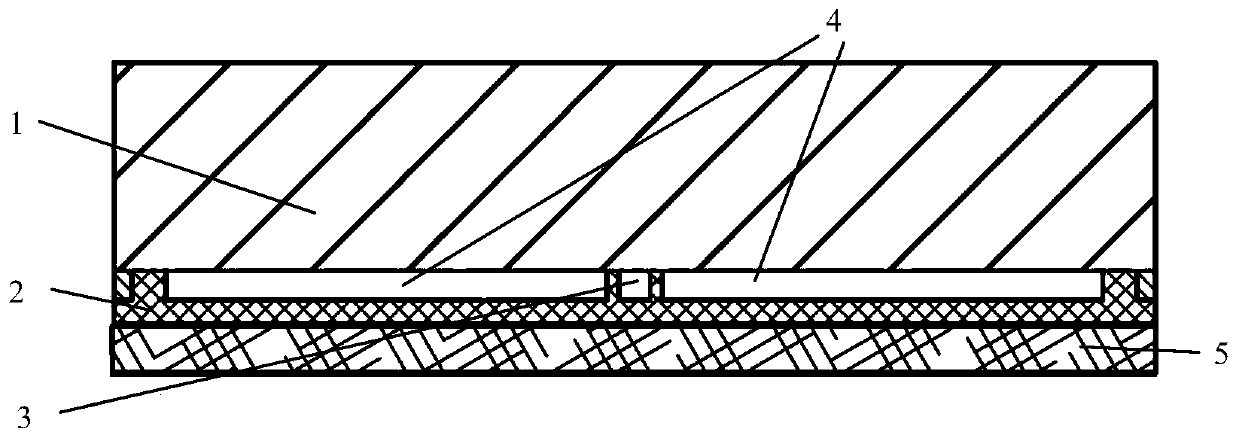
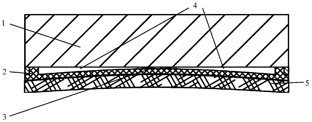
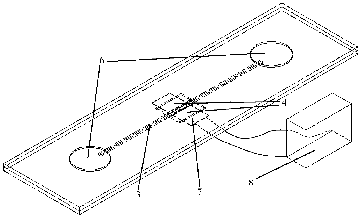
[0025] A microvalve device for a microfluidic chip, such as figure 1 , 2 , 3 and 4, including a cover sheet 1, an elastic material layer 2 and a deformable device layer 5, the elastic material layer 2 is located between the cover sheet 1 and the deformable device layer 5, and the elastic material layer 2 is in the middle of the cover sheet 1 An independent liquid flow channel 3 and a cavity 4 are provided, and the cavity 4 is located on both sides of the liquid flow channel 3, and the elastic material layer 2 can be elastically deformed under the extrusion or pulling of the deformable device layer 5, thereby Control the closing and opening of the liquid passage 3.
[0026] In addition, it also includes two round holes 6 arranged on the surface of the cover sheet 1 , which are respectively connected to the openings at both ends of the liquid passage 3 .
[0027] The deformable device layer 5 is a piezoelectric film 7 connected to an electrical signal generating device 8 .
Embodiment 2
[0029] Such as image 3 As shown, using PDMS material, mix the prepolymer and curing agent at a ratio of 10:1, and pour it into the prepared mold. The heights of the above-mentioned protrusions can be the same or different. The PDMS was degassed and then heated to 85°C to solidify, forming a structure consisting of a longer groove and shorter grooves on both sides. A laser engraving machine is used to engrave two circular holes 6 on a piece of glass, and the relative positions of the centers of the two circular holes 6 correspond to the two endpoints of the linear pattern on the surface of the PDMS.
[0030] Align the round hole on the glass sheet with the two ends of the straight line on the PDMS, and the patterned side of the above PDMS is bonded to the glass sheet to form a straight channel (liquid flow channel 3) and two flow channels that can be used for liquid flow operations. Side airtight cavity 4. Cover the surface of the PDMS chip with a piece of deformable device...
Embodiment 3
[0033] According to the method of Example 1, glue the deformable device 5 (piezoelectric film 7 ) to the PDMS surface, and adjust the piezoelectric film 7 to bend in the direction of the liquid passage 3 in advance to make a normally closed valve structure. When no voltage is applied to the piezoelectric film 7, the piezoelectric film 7 squeezes the flow channel, and the upper and lower surfaces of the liquid-passing flow channel 3 fit together, and the fluid cannot pass through. When the electrical signal generating device 8 is used to apply a potential difference opposite to that of Example 1 to the piezoelectric film 7, the center of the piezoelectric film 7 deforms away from the flow channel, so that the upper and lower surfaces of the flow channel 3 are separated, and the fluid can flow normally at this time.
PUM
 Abstract
Description
Claims
Application Information
 - R&D
- Intellectual Property
- Life Sciences
- Materials
- Tech Scout
- Unparalleled Data Quality
- Higher Quality Content
- 60% Fewer Hallucinations
Browse by: Latest US Patents, China's latest patents, Technical Efficacy Thesaurus, Application Domain, Technology Topic, Popular Technical Reports.
© 2025 PatSnap. All rights reserved.Legal|Privacy policy|Modern Slavery Act Transparency Statement|Sitemap|About US| Contact US: help@patsnap.com


