Novel flooded type evaporating heat exchange tube

A heat exchange tube, flooded technology, used in evaporators/condensers, tubular elements, heat transfer modification, etc. The effect of increasing the growth and improving the boiling heat transfer coefficient

Active Publication Date: 2019-02-05
山东恒辉节能技术集团有限公司
View PDF9 Cites 0 Cited by
  • Summary
  • Abstract
  • Description
  • Claims
  • Application Information

AI Technical Summary

Problems solved by technology

However, the heat transfer coefficient of this heat exchange tube is lower than that of the current conventional commercial tube, and it is rarely found in the market
There are several deficiencies in this evaporative heat exchange tube technology: First, the geometric size of the gap between adjacent fins is not easy to control in manufacturing, and it extends along the circumferential direction, which is converted into an exhaust port. Compared with the current conventional commercial tubes , the area is too large
The reason is that the root of the "T" fin forms a 90-degree angle with the bottom surface of the cavity and the cavity volume is large

Method used


Image

  • Novel flooded type evaporating heat exchange tube
  • Novel flooded type evaporating heat exchange tube
  • Novel flooded type evaporating heat exchange tube

Examples


Embodiment

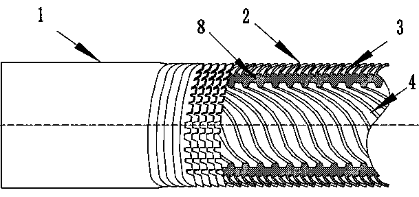
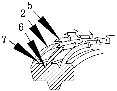
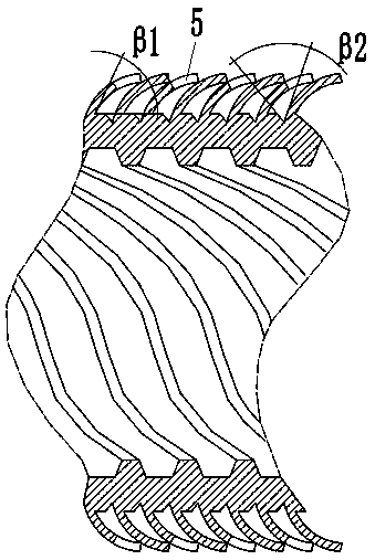
[0026] Embodiment: a new flooded evaporative heat exchange tube (see Figure 1-Figure 3), which includes light segment 1 and evaporation surface segment. Optical section 1 is used for fixing with the end plate of the heat exchanger, and its outer diameter is 19mm. The evaporation surface section is the heat exchange surface, and the evaporation surface section includes the heat exchange tube body 8, and the outer surface of the heat exchange tube body 8 is provided with inclined and curved fins 2 distributed in a spiral shape along the axis of the heat exchange tube, and the surface of the fins 2 is Curved surface shape, and the fins are inclined in the same direction. The tops of adjacent fins 2 are in close contact with each other without gaps. The length of fins 2 is 0.8-1.1mm, and the thickness of fins 2 is 0.08-0.25mm. The root spacing is 0.3-0.8mm. The fins 2 cover the channels between the fins to form a triangular cavity 3, the height of the cavity 3 is 0.3-0.5mm, and...


PUM


Abstract

The invention discloses a novel flooded type evaporating heat exchange tube. The novel flooded type evaporating heat exchange tube comprises a light section and an evaporating surface section, whereinthe evaporating surface section comprises a heat exchange tube body (8). The novel flooded type evaporating heat exchange tube is characterized in that inclined bent fins (2) which are spirally distributed along the axis of the heat exchange tube are arranged on the outer surface of the heat exchange tube body (8), wherein the surfaces of the fins (2) are in the shapes of curved surfaces, and thefins tilt in the same direction; the tops of adjacent fins (2) are in tight contact with each other without a seam, and the fins (2) cover a channel between the fins to define a triangular cavity (3); a trapezoidal notch (5) is formed in the top of each fin (2) as a steam discharge hole/liquid inlet of the cavity; and bulged ribs which are uniformly distributed in the peripheral direction are arranged on the inner surface of the heat exchange tube body (8), and a spiral channel is formed between every two adjacent ribs. The novel flooded type evaporating heat exchange tube is simple in processing, and is high in yield; and within a practical common wall surface superheat degree range, a heat exchange coefficient is slightly affected by the wall surface superheat degree, and is kept stable, so that variable working conditions of a heat exchanger are adapted.

Description

Technical field: [0001] The invention relates to a heat transfer tube for an evaporator, in particular to a novel flooded evaporation heat exchange tube, which is suitable for the evaporator of a chiller in a central air-conditioning system. Background technique: [0002] In the central air-conditioning system, the flooded evaporator is an important equipment of the chiller. In the flooded evaporator, the heat exchange tube is immersed in the refrigerant. When the circulating water with relatively high temperature passes through the tube, it exchanges heat with the refrigerant outside the tube, and the low-temperature refrigerant boils. In order to enhance the heat exchange, many high-efficiency heat exchange tubes manufactured by specialized technology have been produced. The high-efficiency heat exchange tube with "T" shape structure that is popular in business is a typical enhanced heat exchange tube. Its manufacturing process and characteristics are as follows: Firstly...

Claims


Application Information

Patent Timeline
Patent Type & Authority Applications(China)
IPC IPC(8): F25B39/02F28F1/12F28F1/36F28F1/40F28F13/00
CPCF25B39/02F28F1/126F28F1/36F28F1/40F28F13/00
Inventor 李小利王斌马青川李玉海董桂梅张俊峰任鼎何璇张占波
Owner 山东恒辉节能技术集团有限公司
Why Eureka
Try Eureka