Flange for an electrical machine

A flange and chamber technology, applied in the field of motors, can solve problems such as the difficulty of effectively cooling the winding head, and achieve the effects of ensuring battery life, ensuring sealing, and increasing performance

Inactive Publication Date: 2019-02-05
INST VEDECOM
View PDF5 Cites 0 Cited by
  • Summary
  • Abstract
  • Description
  • Claims
  • Application Information

AI Technical Summary

Problems solved by technology

Given this reduction in motor size, it becomes particularly difficult to cool the winding heads effectively

Method used


Image

  • Flange for an electrical machine
  • Flange for an electrical machine
  • Flange for an electrical machine

Examples


Embodiment Construction

[0058] At the outset it is noted that the accompanying drawings show the invention in detail in order to realize it, said drawings can of course be used to better define the invention if necessary. Reference numerals remain the same from one figure to another.

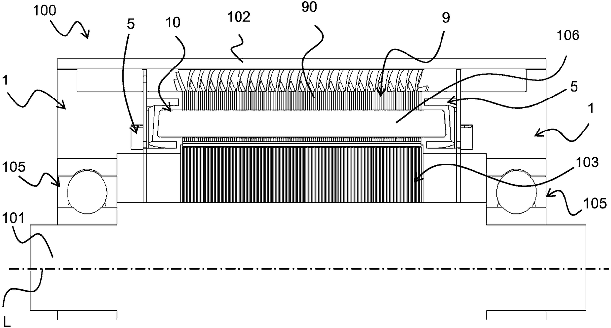
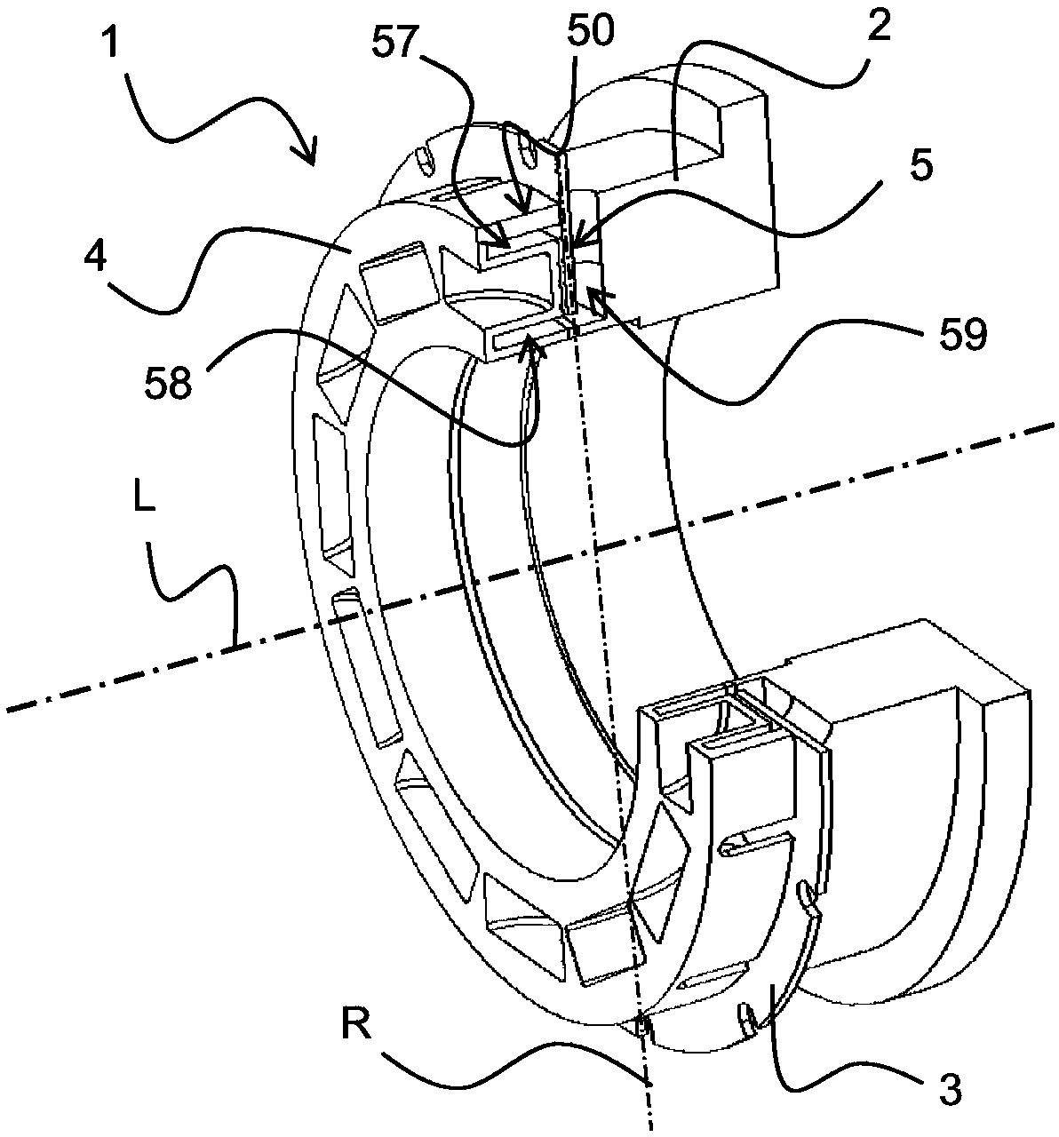
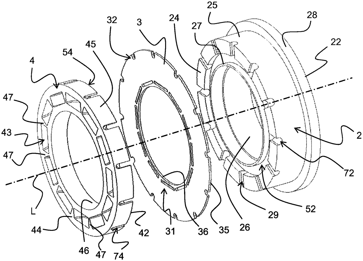
[0059] In the following description, relative terms (eg "inner" or "outer") are defined relative to the flange and / or the longitudinal axis L of the motor. The term "inner" along this longitudinal axis means that the considered element is located inside or directed towards the inside of the machine, while the term "external" along the longitudinal axis means that the considered element is located outside or directed towards the outside of the machine. Relative terms (e.g. "inner", "outer") are defined relative to the radius R of the flange and / or motor, the "inner" concept is close to the center of the flange and / or motor, and the "outer" concept is away from the center, the center May for example be defined by a long...


PUM


Abstract

The invention relates to a flange (1) for an electrical machine (100), said flange being configured to at least partially cover winding overhangs (10) that form part of the electrical machine (100), the flange (1) comprising a chamber (5) able to receive a cooling fluid, characterized in that the flange (1) comprises at least one first orifice and at least one second orifice allowing cooling fluidto enter the chamber (5) or allowing cooling fluid to leave the chamber (5), said chamber (5) having a profile that compliments that of at least one winding overhang (10). The flange is applicable tomotor vehicles.

Description

[0001] This application claims priority from French application 1654310, filed May 13, 2016, the disclosure of which (text, drawings and claims) is hereby incorporated by reference in its entirety. technical field [0002] The field of the invention is that of electric machines, preferably rotating electric machines, such as generators or engines. More specifically, these electric machines are intended to be mounted on vehicles, especially motor vehicles such as road vehicles or trains. Background technique [0003] A rotating electrical machine, such as a generator or engine, includes a stator and a rotor. Coils (enroulements) forming windings (bobines) are assembled on the stator, and permanent magnets are fixed on the rotor. The rotor is rotatably movable by means of a shaft. The rotational movement of the rotor against the stator windings generates electrical energy when the electric machine is a generator, and mechanical energy when the electric machine is a motor. ...

Claims


Application Information

Patent Timeline
Patent Type & Authority Applications(China)
IPC IPC(8): H02K3/52H02K3/24H02K9/197H02K1/20H02K5/20
CPCH02K1/20H02K3/522H02K9/197H02K3/24H02K5/203
Inventor T·阿米提G·迪耶蒙施D·洛泰利耶
Owner INST VEDECOM
Why Eureka
Try Eureka