
Semi-active vibration isolation device

A semi-active, vibration-isolation technology, applied in the direction of springs, magnetic springs, springs/shock absorbers, etc., can solve the problems of difficult structure miniaturization, increased control system complexity, and large range of current regulation.

Active Publication Date: 2019-02-12
CHINA UNIV OF MINING & TECH
View PDF6 Cites 4 Cited by
  • Summary
  • Abstract
  • Description
  • Claims
  • Application Information

AI Technical Summary

Problems solved by technology

For example, the invention patent (publication number CN108019452A) discloses a semi-active controllable stiffness nonlinear electromagnetic vibration isolator, the principle of which is to realize the control of damping and nonlinear stiffness by adjusting the size of the variable resistance and variable inductance , although the vibration isolator has the advantage of large control force, it needs to control two quantities at the same time, which increases the complexity of the control system; the invention patent (publication number CN107606018A) discloses an hourglass type electromagnetic vibration isolator. Small current required, large output displacement, adjustable stiffness, compact structure, and strong designability, but it achieves the purpose of vibration isolation by changing the direction of the current in the coil by turning on and off the power, the current adjustment range is large, and the structure Difficult to miniaturize, limited application

Method used


Image

  • Semi-active vibration isolation device
  • Semi-active vibration isolation device
  • Semi-active vibration isolation device

Examples


Embodiment Construction

[0024] The present invention will be further described below in conjunction with accompanying drawing.

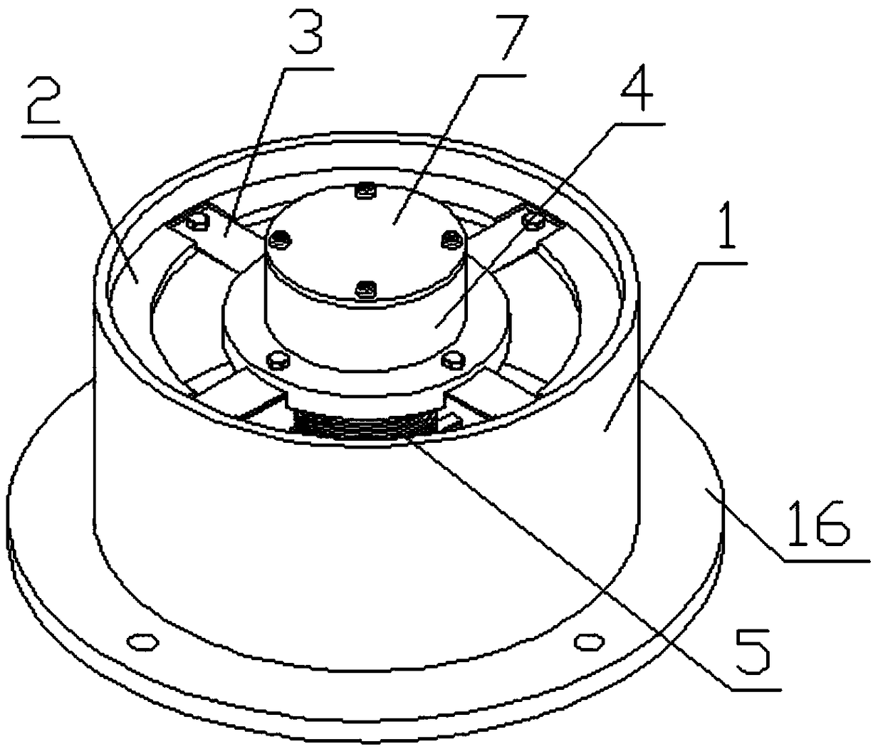
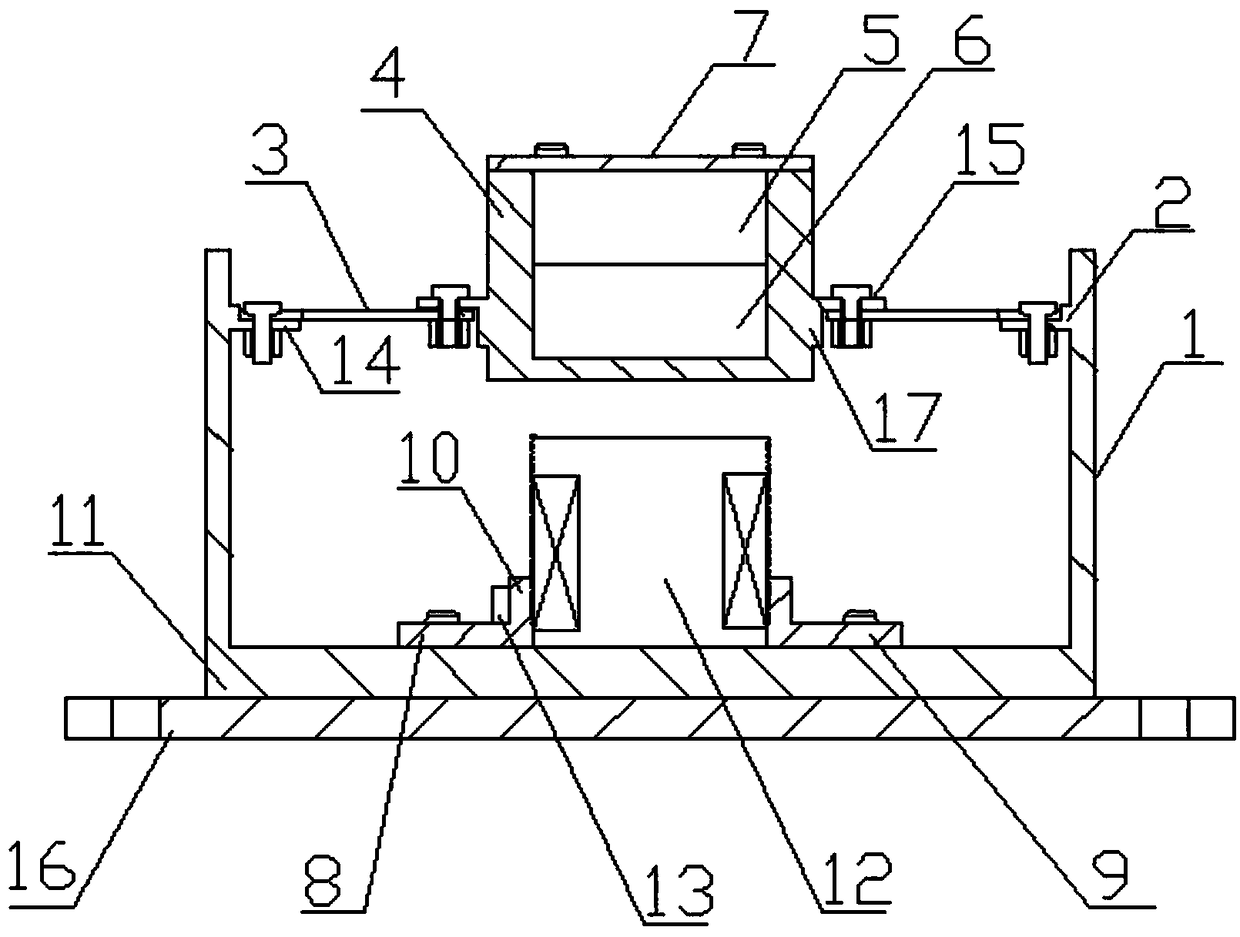
[0025] Such as figure 1 and figure 2 As shown, a semi-active vibration isolation device includes a cylindrical shell 1 with an open upper end, an electromagnet 12 located inside the cylindrical shell 1, and a displacement monitoring and control system. The bottom of the cylindrical shell 1 is closed by a bottom plate 11, The cylindrical shell 1 is provided with an annular connecting plate 2 near the opening of the upper end, and the outer circumference of the annular connecting plate 2 is fixedly connected with the inner wall of the cylindrical shell 1; the thickness of each part of the annular connecting plate 2 in the circumferential direction is equal . As a preference, the annular connecting plate 2 can be integrally formed inside the cylindrical casing 1 .

[0026] The inner center of the annular connecting plate 2 is provided with a stage 4; the stage 4 and the an...


PUM


Abstract

The invention discloses a semi-active vibration isolation device. The bottom of a barrel-shaped shell body is sealed by a bottom plate, an annular connection plate is arranged at a position close to an upper-end opening, in the barrel-shaped shell body, and the outer circumference of the annular connection plate is fixedly connected with the inner wall of the barrel-shaped shell body; a carrying table is arranged at the inner center of the annular connection plate; the carrying table is connected with the annular connection plate through a plurality of straight-sheet springs; a permanent magnet is assembled in the carrying table; an electromagnet and the permanent magnet are correspondingly and fixedly installed on the bottom plate, an air gap is reserved between the electromagnet and thepermanent magnet, and the upper end of the electromagnet has the same magnetic pole as the lower end of the permanent magnet after being electrified; and a displacement monitoring control system is composed of a displacement sensor, a signal converter, a current controller and an intelligent control terminal, the displacement sensor is fixedly arranged below the carrying table, the displacement sensor is connected with an input end of the intelligent control terminal through the signal converter, and an output end of the intelligent control terminal is connected with the electromagnet throughthe current controller. The device is simple and compact in structure, easy to control, and good in vibration isolation effect.

Description

technical field [0001] The invention relates to a vibration isolator, in particular to a semi-active vibration isolation device, which belongs to the technical field of vibration control. Background technique [0002] Vibration isolation (referred to as vibration isolation) technology is the most widely used technology in the field of vibration control, and has a wide range of applications in civil engineering, aerospace, automobiles, ships, precision manufacturing and processing. Vibration isolation technology can be divided into passive vibration isolation, active vibration isolation and semi-active vibration isolation. Among them, semi-active vibration isolation technology has better vibration isolation performance than passive vibration isolation technology, especially in the low frequency range. At the same time, it is different from active vibration isolation technology. In contrast, semi-active vibration isolation does not bring a large amount of energy demand, and th...

Claims


Application Information

Patent Timeline
IPC IPC(8): F16F6/00
CPCF16F6/00
Inventor 徐嘉伟杨雪锋郑嘉毓李威王禹桥范猛豹卢昱瑾周文韬郑威许少毅
Owner CHINA UNIV OF MINING & TECH
Learn More