
Coaxial spatial optical receiving-transmitting communication device

A technology of communication devices and spatial light, which is applied in electromagnetic transceivers, optical components, light guides, etc., can solve the problems of small alignment tolerance and complex alignment operations, and achieve reduction requirements, save occupied volume, and increase light spots area effect

Inactive Publication Date: 2019-02-12
HISENSE & JONHON OPTICAL ELECTRICAL TECH CO LTD
View PDF5 Cites 11 Cited by
  • Summary
  • Abstract
  • Description
  • Claims
  • Application Information

AI Technical Summary

Problems solved by technology

[0005] In order to solve the technical problems that the existing ground space optical communication components can only perform one-way communication, the alignment tolerance is small, and the alignment operation is complicated, the present invention proposes a coaxial space optical transceiver communication device, which can solve the above problems

Method used


Image

  • Coaxial spatial optical receiving-transmitting communication device
  • Coaxial spatial optical receiving-transmitting communication device
  • Coaxial spatial optical receiving-transmitting communication device

Examples


Embodiment 1

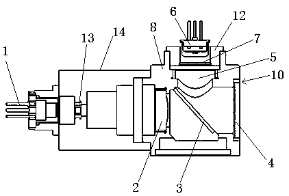
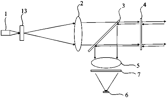
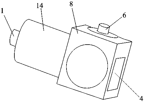
[0032] Embodiment 1, this embodiment proposes a coaxial space optical transceiver communication device, the optical path of which is as follows Figure 1-Figure 3 shown, including:

[0033] Laser 1, used to generate and emit laser signals;

[0034] The collimating lens 2 is used to convert the exit angle of the emitted laser signal, and emit through the first beam splitter 3 and the light window 4 in sequence;

[0035] The first beam splitter 3 is used to transmit the emitted laser signal and reflect the received laser signal;

[0036] The light window 4 is used for transmitting the emitted laser signal and transmitting the received laser signal;

[0037] The converging lens 5 is located on the reflection optical path after the received laser signal is reflected by the first beam splitter 3, and is used for converging the received laser signal to the photodetector 6, the photodetector 6 is located at the defocused position of the converging lens 5, and the laser is located a...


PUM


Abstract

The invention discloses a coaxial spatial optical receiving-transmitting communication device. The device comprises a laser device, a collimating lens, a first beam splitter, an optical window and a convergent lens, wherein the laser device is used for generating an emission laser signal and sending out the emission laser signal; the collimating lens is used for transforming an emergent angle of the emission laser signal and the emission laser signal is emitted through the first beam splitter and the optical window; the first beam splitter is used for transmitting the emission laser signal andreflecting a receiving laser signal; the optical window is used for emitting the emission laser signal and transmitting the receiving laser signal; and the convergent lens is located on a reflected optical path formed by reflecting the receiving laser signal through the first beam splitter. According to the coaxial spatial optical receiving-transmitting communication device, a receiving-transmitting coaxial scheme is adopted; emission and receiving optical paths are coaxial, thereby being beneficial to saving an occupation volume of the communication device, and implementing coaxiality of theemission and receiving optical paths; and the collimating lens is laid in a defocusing manner, thereby improving the alignment tolerance capability and reducing the alignment requirement.

Description

technical field [0001] The invention relates to an optical communication device, in particular to a coaxial space optical transceiver communication device. Background technique [0002] The existing terrestrial space optical communication system has a communication distance ranging from tens of meters to several kilometers. The typical size of the optical antenna used is about 300mm*300mm*600mm, and the weight is about 15Kg. Larger in size and weight. And before communication is established, it is necessary to use auxiliary optical systems such as tracking devices, gun sights, or telescopes to debug the optical path. The required auxiliary optical systems are large in size and require a long time for debugging, which takes tens of minutes to several hours. [0003] Ground space optical communication systems are currently on the market with the F-light communication components of the French Radiall Company and the communication components of the American Fsona Communications...

Claims


Application Information

Patent Timeline
Patent Type & Authority Applications(China)
IPC IPC(8): G02B6/42H04B10/40
CPCG02B6/4204G02B6/4215G02B6/4225G02B6/4246H04B10/40
Inventor 张洪涛姜瑜斐曲业飞武玉谦王晨阳王斐
Owner HISENSE & JONHON OPTICAL ELECTRICAL TECH CO LTD
Learn More