
Intelligent balancing lever compensation method and balancing lever machining process using same

A compensation method and processing technology, applied in the field of auto parts processing, can solve problems such as the inability to output the parameters of the end hole of the balance rod in time, the inability to accurately adjust the processing technology in time, the influence of processing accuracy and efficiency, etc., so as to improve the purchasing experience and avoid Large batches of substandard products or scrap, the effect of improving processing accuracy and efficiency

Inactive Publication Date: 2019-02-12
蒂森克虏伯弹簧稳定杆(平湖)有限公司
View PDF6 Cites 3 Cited by
  • Summary
  • Abstract
  • Description
  • Claims
  • Application Information

AI Technical Summary

Problems solved by technology

[0006] When the balance bar is produced and processed according to the above method, the end hole parameters of the balance bar cannot be output in time, and the processing technology (parameters) cannot be adjusted accurately in time, resulting in a large number of unqualified products and even batch scrapping, that is, processing accuracy and efficiency. are greatly affected, so it is necessary to propose a new solution to solve this problem

Method used


Image

  • Intelligent balancing lever compensation method and balancing lever machining process using same
  • Intelligent balancing lever compensation method and balancing lever machining process using same
  • Intelligent balancing lever compensation method and balancing lever machining process using same

Examples


Embodiment 1

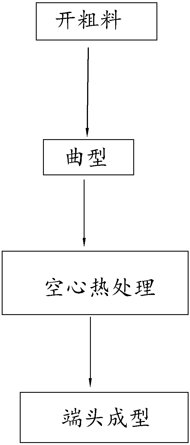
[0059] Embodiment 1, the balance bar intelligent compensation method and the balance bar processing technology using the method, the balance bar processing technology can be divided into: solid balance bar process and hollow balance bar process according to the different types of balance bar processed, and the forming stages of the two are respectively according to The following operations, such as figure 2 with image 3 shown.

[0060] The forming process of solid balance bar includes:

[0061] a1. Preparation, including processing the columnar balance bar rough material by sawing machine, punching machine and other cutting equipment, using heating equipment, generally an intermediate frequency furnace to heat the balance bar rough material, and using an upset forging machine to make the end of the heated balance bar rough material Flattening, trimming, punching, and controlling the total length to prepare the primary material of the balance bar;

[0062] a2. Curved shape...

Embodiment 2

[0102] Embodiment 2, apply the balance bar processing technology of the balance bar intelligent compensation method, refer to Figure 5 with Image 6 ,include:

[0103] A1. Forming, setting and processing the balance bar according to the processing method of the balance bar; the processing method of the balance bar has certain differences according to whether the processed balance bar is hollow or solid, and the operation can be carried out according to the content of the first embodiment.

[0104] A2. Process parameter correction. The numerical control mechanism 2 obtains the end hole position parameters through the feedback mechanism 1, and controls the balance bar processing equipment to correct the processing action according to the balance bar intelligent compensation method. For details, refer to Embodiment 1. The types of balance bars processed are different, and the feedback The installation position of mechanism 1 and the position of collecting information are differ...


PUM


Abstract

The invention discloses an intelligent balancing lever compensation method and a balancing lever machining process using the same, relates to the field of automobile parts machining, and aims at solving the problem that mass unqualified or scrapped products appear as existing balancing lever production data feedback is not timely and process parameters cannot be adjusted timely. The key point of the technical scheme is that a feedback mechanism is arranged to acquire and feedback balancing lever parameters, a numerical-control mechanism is connected with a balancing lever machining device andused for controlling the balancing lever machining device, acquiring balancing lever production parameters through the feedback mechanism, and controlling the machining device to automatically correctthe machining actions by utilizing the numerical-control mechanism according to the production parameters so as to improve process parameters. The method and the process are capable of improving thebalancing lever machining precision and efficiency and effectively preventing the products from being massively unqualified or scrapped.

Description

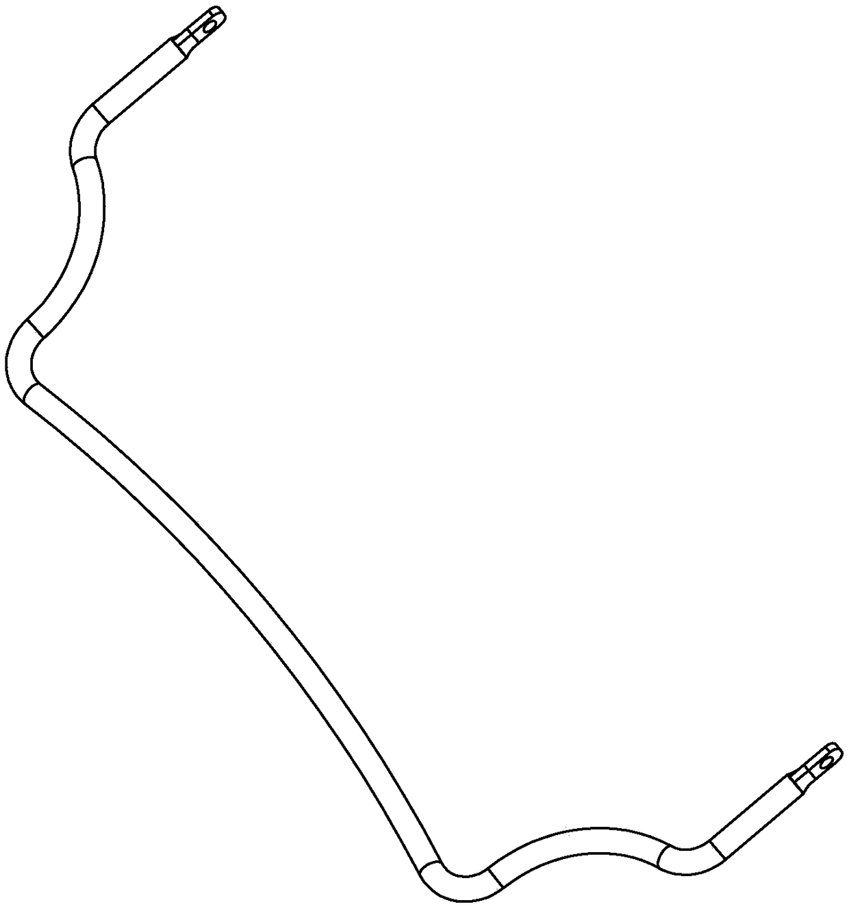
technical field [0001] The invention relates to the field of auto parts processing, more specifically, it relates to an intelligent compensation method for a balance bar and a process for processing the balance bar using the method. Background technique [0002] The balance bar is an important part of the car, which is mainly used to generate anti-roll resistance and restrain the body from rolling. [0003] balance bar, such as figure 1 The one shown includes a shaft. The end of the shaft is bent into a certain shape, and a fixing hole is opened at the end of the shaft. [0004] When the stabilizer bar is installed on the car, the horizontal position of the bar body and the hole position at the end all need to be fixed. Since the position of the end hole has a certain three-dimensional difference with respect to the horizontal position of the shaft, this leads to high precision requirements for the balance bar to ensure that the end hole can also be fixed at the specified ...

Claims


Application Information

Patent Timeline
Patent Type & Authority Applications(China)
IPC IPC(8): G05B19/418
CPCG05B19/4185G05B2219/31088Y02P90/02
Inventor 方和平
Owner 蒂森克虏伯弹簧稳定杆(平湖)有限公司
Learn More