Blast furnace flushing slag flue gas whitening integrated device

A blast furnace slag flushing and flue gas technology, applied in chemical instruments and methods, dispersed particle separation, separation methods, etc., can solve problems such as white plume, and achieve the effects of flexible land occupation, important application value, and simple structure

Active Publication Date: 2019-02-15
HEIMDALLR SHANGHAI ENERGY SAVING TECH
View PDF13 Cites 5 Cited by
  • Summary
  • Abstract
  • Description
  • Claims
  • Application Information

AI Technical Summary

Problems solved by technology

[0003] However, while the blast furnace slag flushing water recovers waste heat, the smoke exhaust of the ironmaking blast furnace slag flushing water produces serious white feathers

Method used


Image

  • Blast furnace flushing slag flue gas whitening integrated device
  • Blast furnace flushing slag flue gas whitening integrated device

Examples


Embodiment 1

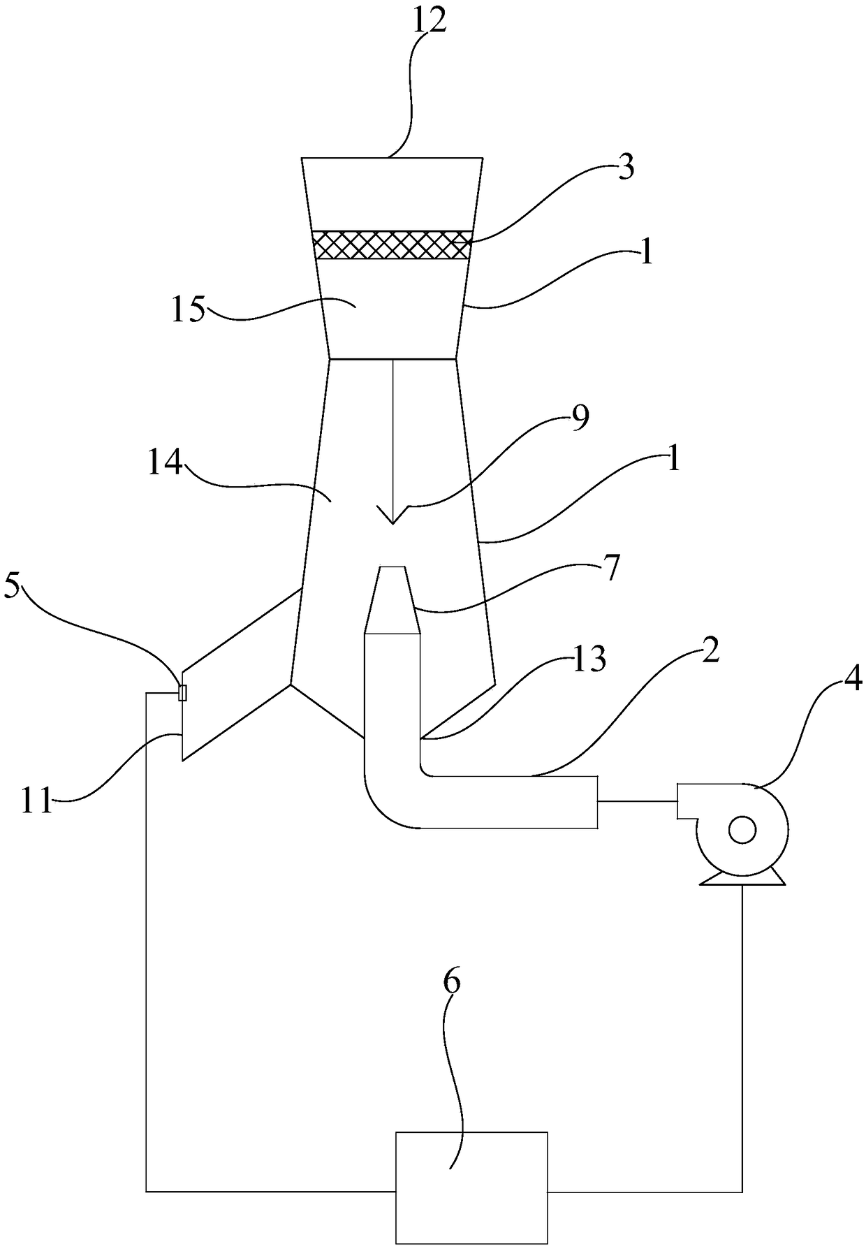
[0035] like figure 1 As shown, this embodiment discloses a blast furnace slag flushing flue gas whitening integrated device, the blast furnace slag flushing flue gas whitening integrated device includes a shell 1 and a hot air pipe 2, and the shell 1 includes a mixing zone 14 , the housing 1 is provided with a flue gas inlet 11, a flue gas outlet 12 and a hot blast inlet 13, the flue gas outlet 12 is located above the mixing zone 14, the flue gas inlet 11 and the hot blast inlet 13 are located at the bottom of the mixing zone 14, and the hot blast duct 2 Connected to the hot air inlet 13 and communicated with the mixing zone 14. The blast furnace slag flushing flue gas enters the mixing area 14 of the shell 1 through the flue gas inlet 11, and the external hot air is transported to the hot air inlet 13 through the hot air pipe 2, and then enters the mixing area 14 of the shell 1 through the hot air inlet 13. The blast furnace slag flushing flue gas will be mixed with the exte...

Embodiment 2

[0054] The difference between this embodiment and Embodiment 1 is that the blast furnace slag flushing and flue gas whitening integrated device of this embodiment does not include a dust collector 3, and the blast furnace slag flushing flue gas whitening integrated device of this embodiment includes Lifting air cap 9, rising air cap 9 is located in mixing zone 14, and rising air cap 9 is positioned at the top of hot air inlet 13. The hot blast enters into the mixing zone 14 through the hot blast inlet 13 and the nozzle 7, the tip of the air lift cap 9 faces down and is positioned directly above the nozzle 7, the hot blast will flow to the air lift cap 9 and spread out, and the entrainment in the hot air Moisture will be blocked on the gas-lifting cap 9, which improves the whitening effect of the blast furnace slag flushing flue gas whitening integrated device. At the same time, the furnace slag flue gas and hot air will be diffused through the gas lift cap 9, so that the furna...


PUM


Abstract

The invention discloses a blast furnace flushing slag flue gas whitening integrated device. The blast furnace flushing slag flue gas whitening integrated device comprises a shell and a hot air pipe, wherein a mixing zone is arranged inside the shell; a flue gas inlet, a flue gas outlet and a hot air inlet are formed in the shell; the flue gas outlet is formed above the mixing zone; the flue gas inlet and the hot air inlet are formed in the bottom of the mixing zone; and the hot air pipe is connected to the hot air inlet and is communicated with the mixing zone. Blast furnace flushing slag fluegas enters the mixing zone through the flue gas inlet, hot air enters the mixing zone through the hot air pipe, and the blast furnace flushing slag flue gas and the hot air are mixed in the mixing zone, so that the dew point of mixed flue gas is lowered, the dry-bulb temperature thereof is raised, no white smoke plume is emitted when the mixed flue gas is discharged, and the effect of eliminatingwhite fog is achieved; and meanwhile, the blast furnace flushing slag flue gas whitening integrated device is simple in structure, flexible in land occupation, low in implementation difficulty, low in investment and low in operating cost and has an important application value.

Description

technical field [0001] The invention relates to a blast furnace slag flushing flue gas whitening integrated device. Background technique [0002] In recent years, China's metallurgy has developed rapidly, and the output of pig iron accounts for more than 50% of the world's total output. At the same time, the energy consumption rate of China's metallurgical industry is very high, and there is huge energy-saving space and market potential. With the continuous improvement of energy saving and consumption reduction and comprehensive utilization of resources in iron and steel enterprises, the structure of the energy industry has changed. Strengthening energy optimization, developing circular economy, and utilizing waste heat and energy have become the development trend of iron and steel enterprises. Under the influence of a good environment, the development and utilization of waste heat and waste energy has become common practice, especially the low-temperature waste heat resourc...

Claims


Application Information

Patent Timeline
Patent Type & Authority Applications(China)
IPC IPC(8): B01D53/00
CPCB01D53/005Y02W30/50
Inventor 白亮叶晨涛赵怀超
Owner HEIMDALLR SHANGHAI ENERGY SAVING TECH
Why Eureka
Try Eureka