Multifunctional intelligent cloth pulling system

An intelligent spreading and multi-functional technology, applied in the direction of winding strips, thin material handling, transportation and packaging, etc., can solve the problems of uneven pressure, insufficient durability, limited diameter of rollers, etc., to improve work efficiency, The effect of high cloth quality and large feeding force

Pending Publication Date: 2019-02-15
福建省和达智能科技有限公司
View PDF0 Cites 1 Cited by
  • Summary
  • Abstract
  • Description
  • Claims
  • Application Information

AI Technical Summary

Problems solved by technology

[0002] The existing pulling system is to use two cylindrical rollers, the rollers are covered with rubber material to increase the friction, and then the two rollers are used to clamp the woven cloth, and the two rollers rotate in opposite directions, and the friction is used to carry out the process. Pulling, such a pulling system will exist: 1. Due to the limitation of installation space, the diameter of the roller is limited, resulting in insufficient rigidity of the roller, resulting in uneven pressure; 2. The pulling force cannot continue to increase; 3. The coefficient of friction is difficult Control; 4. The wrapping material will be worn out with the operation of the machine, the service life is short, and the durability is insufficient; 5. The phenomenon of sticking thread ends is prone to occur, and cloth rolling will occur, which will affect the quality of the cloth and production efficiency. Therefore, we propose a New multi-functional intelligent cloth pulling system

Method used


Image

  • Multifunctional intelligent cloth pulling system
  • Multifunctional intelligent cloth pulling system
  • Multifunctional intelligent cloth pulling system

Examples


Embodiment 1

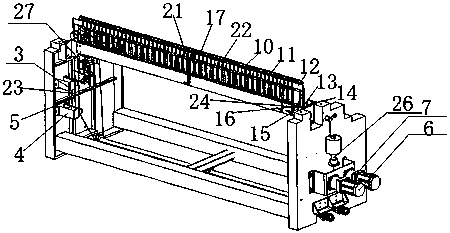
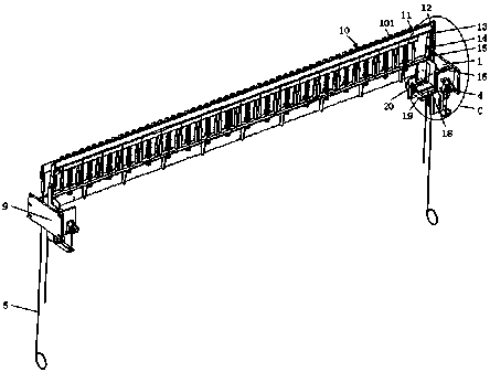
[0028] 1. When the splint A "opens" the electromagnet 18 is de-energized and released, and the splint A "closes" the electromagnet 19 is activated;

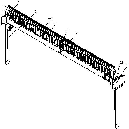
[0029] 2. The A splint 11 uses the A splint drive pin 14 as the fulcrum to perform positive lever movement, and the B splint 10 clamps the woven cloth piece one by one;

[0030] 3. A splint drives the servo motor 6 to rotate forward, drives the A splint wire rope 5 to pull the A splint drive arm 15, the A splint drive pin 14 and the A splint 11 move down from the initial position along the guide rail 16 simultaneously, and the B splint 10 is on the side of the A splint 11 Move down passively under action;

[0031] 4. Under the combined action of the A splint 11 and the B splint 10, the pull-down action of the woven cloth sheet is completed;

[0032] 5. A splint "closes" the electromagnet 19 is de-energized and releases, and the splint A "opens" the electromagnet 18 gets electric action;

[0033] Sixth, the A splint 11 makes a r...

Embodiment 2

[0036]1. When the splint A "opens" the electromagnet 18 is de-energized and released, and the splint A "closes" the electromagnet 19 is activated;

[0037] 2. The A splint 11 uses the A splint drive pin 14 as the fulcrum to perform positive lever movement, and the B splint 10 clamps the woven cloth piece one by one;

[0038] 3. A splint drives the servo motor 6 to rotate forward, press down the A splint lifting spring 27 to drive the A splint wire rope 5 to pull the A splint drive arm 15, the A splint drive pin 14 and the A splint 11 from the initial position to move down along the guide rail 16 simultaneously, B The splint 10 passively moves down under the action of the A splint 11;

[0039] 4. Under the combined action of the A splint 11 and the B splint 10, the pull-down action of the woven cloth sheet is completed;

[0040] 5. A splint "closes" and the electromagnet 19 is de-energized and released, and the A splint 11 "opens" and the electromagnet 18 is powered;

[0041]...

Embodiment 3

[0044] 1. A splint 11 is "opened" and the electromagnet 18 is de-energized and released, and the splint A is "closed" and the electromagnet 19 is powered;

[0045] 2. The A splint 11 uses the A splint drive pin 14 as the fulcrum to perform positive lever movement, and the B splint 10 clamps the woven cloth piece one by one;

[0046] 3. A splint drives the servo motor 6 to rotate forward, press down the A splint to raise the counterweight 26, pull the A splint wire rope 5 to drive the A splint drive arm 15, the A splint drive pin 14 and the A splint 11 to move down from the initial position along the guide rail at the same time, B The splint 10 passively moves down under the action of the A splint 11;

[0047] 4. Under the combined action of the A splint 11 and the B splint 10, the pull-down action of the woven cloth sheet is completed;

[0048] 5. A splint "closes" the electromagnet 19 is de-energized and releases, and the splint A "opens" the electromagnet 18 gets electric a...


PUM


Abstract

The invention discloses a multifunctional intelligent cloth pulling system. The multifunctional intelligent cloth pulling system comprises a left mounting plate and a right mounting plate. Guide railsare arranged on the inner sides of the left mounting plate and the right mounting plate. A movable sliding block is arranged on each guide rail. A clamping plate A driving arm is fixed on each sliding block. Clamping plate A driving pins are fixed on the clamping plate A driving arms. The clamping plate A driving pins are movably connected with a clamping plate A. The bottom of the clamping plateA is fixedly connected with a clamping plate A rotating mechanism. The bottom of the clamping plate A rotating mechanism is fixedly connected with an electromagnet for opening the clamping plate A and an electromagnet for closing the clamping plate A. The multifunctional intelligent cloth pulling system has a common working mode and an intelligent working mode, wherein the intelligent working mode is based on the common working mode. A clamping plate B drives a servo motor to pull a clamping plate B through a clamping plate B steel wire rope, a clamping plate B pulling arm and a clamping plate B pull-down cross plate, so that pull-down actions at different positions under different pressures can be realized, and the cloth pulling function of various tension force requirements can be met.

Description

technical field [0001] The invention relates to the technical field of textiles, in particular to a multifunctional intelligent cloth pulling system. Background technique [0002] The existing pulling system is to use two cylindrical rollers, the rollers are covered with rubber material to increase the friction, and then the two rollers are used to clamp the woven cloth, and the two rollers rotate in opposite directions, and the friction is used to carry out the process. Pulling, such a pulling system will exist: 1. Due to the limitation of installation space, the diameter of the roller is limited, resulting in insufficient rigidity of the roller, resulting in uneven pressure; 2. The pulling force cannot continue to increase; 3. The coefficient of friction is difficult Control; 4. The wrapping material will be worn out with the operation of the machine, the service life is short, and the durability is insufficient; 5. The phenomenon of sticking thread ends is prone to occur,...

Claims


Application Information

Patent Timeline
Patent Type & Authority Applications(China)
IPC IPC(8): B65H23/028
CPCB65H23/028
Inventor 黄向阳
Owner 福建省和达智能科技有限公司
Why Eureka
Try Eureka