Ultra-light composite beam structure suitable for large-span bridge and construction method of ultra-light composite beam structure suitable

A composite beam and ultra-light technology, applied in bridges, bridge parts, bridge materials, etc., can solve the problems of high cost of UHPC, high tensile stress at joints, and reduced tensile strength, achieving small pouring volume and less welding volume , to avoid the effect of shrinkage cracks

Pending Publication Date: 2019-02-15
邵旭东
View PDF0 Cites 14 Cited by
  • Summary
  • Abstract
  • Description
  • Claims
  • Application Information

AI Technical Summary

Problems solved by technology

However, due to the high cost of UHPC, the economic advantages of UHPC cannot be fully utilized by using a thicker plate thickness, and in the actual bridge structure, the vertical and horizontal forces of the bridge deck are different, generally in one direction (generally longitudinal) , but only using flat-type pure UHPC boards as bridge decks will inevitably result in excess

Method used


Image

  • Ultra-light composite beam structure suitable for large-span bridge and construction method of ultra-light composite beam structure suitable
  • Ultra-light composite beam structure suitable for large-span bridge and construction method of ultra-light composite beam structure suitable
  • Ultra-light composite beam structure suitable for large-span bridge and construction method of ultra-light composite beam structure suitable

Examples


Embodiment Construction

[0055] In order to facilitate the understanding of the present invention, the present invention will be described in more detail below in conjunction with the accompanying drawings and preferred embodiments, but the protection scope of the present invention is not limited to the following specific embodiments.

[0056] Unless otherwise defined, all technical terms used hereinafter have the same meanings as commonly understood by those skilled in the art. The terminology used herein is only for the purpose of describing specific embodiments, and is not intended to limit the protection scope of the present invention.

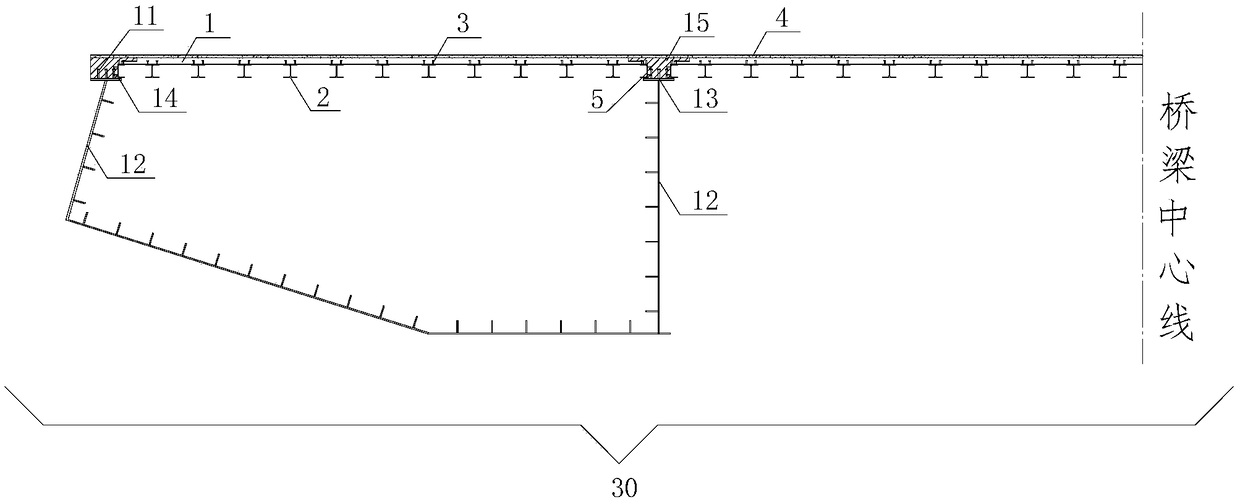
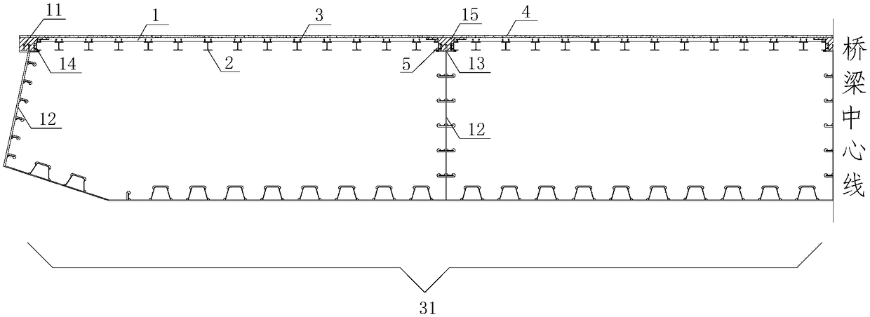
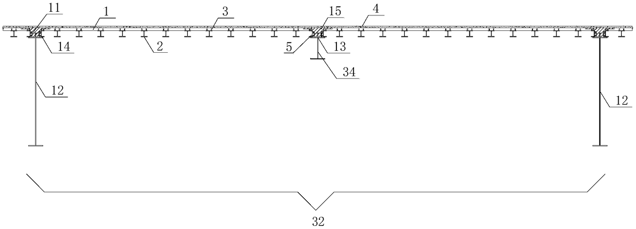
[0057] refer to Figure 1-8 , Figures 12 to 18 , an ultra-light composite beam structure suitable for long-span bridges in this embodiment, the ultra-light composite beam structure is mainly composed of a lower steel beam and an upper section steel-UHPC light composite bridge deck unit.

[0058] The steel girder can be PK steel girder 30, steel box girder 31, s...


PUM

PropertyMeasurementUnit
The average thicknessaaaaaaaaaa
Heightaaaaaaaaaa
Horizontal spacingaaaaaaaaaa

Abstract

The invention discloses an ultra-light composite beam structure suitable for a large-span bridge and a construction method of the ultra-light composite beam structure. The ultra-light composite beam structure is mainly composed of steel beams and bridge deck slab units, wherein bridge deck slab unit comprise profile steel-UHPC light composite bridge deck slabs and peripheral seam constructions; the profile steel-UHPC light composite bridge deck slabs are composed of UHPC plates and profile steel, the profile steel used as longitudinal rib is arranged at the bottoms of the UHPC plates; and thelongitudinal and transverse seam constructions are T-shaped seams. The ultra-light composite beam structure suitable for the large-span bridge has the advantages that the cost is low, the welding amount is little, and risks of fatigue cracking are greatly reduced; meanwhile, the anti-bending inertia moment is higher, the cracking risk of the bridge deck slabs is reduced, fracture in a high tensilestress area is avoided, and the shrinkage fracture is further avoided; the longitudinal and transverse stiffness is convenient to match, self-weight of the bridge deck slabs is reduced, and the requirement of lifting capacity on site is not high; and the construction risk is reduced, the pouring amount on site is small, the workload of dabbing is small, a steel bar at a seam position does not need to be bound, the operation is simple, and the construction is easy.

Description

technical field [0001] The invention belongs to the technical field of bridge components and construction thereof, in particular to an ultra-light composite beam structure suitable for long-span bridges and a construction method thereof. Background technique [0002] Traditional steel-concrete composite beams have a reasonable force and make full use of the advantages of steel in tension and concrete in compression, so that the performance of the combination is better than the simple superposition of the properties of the two materials, so it has good technical and economic benefits. However, with the increase of bridge span, when steel-concrete composite beams are applied to continuous system bridges and long-span flexible system bridges, the negative bending moment area faces the risk of tensile cracking of the upper edge concrete, while the conventional anti-corrosion The effect of cracking measures is not ideal. [0003] In the traditional composite girder cable-stayed ...

Claims


Application Information

Patent Timeline
IPC IPC(8): E01D2/04E01D19/06E01D21/00
CPCE01D2/04E01D19/06E01D21/00E01D2101/268
Inventor 邵旭东李玉祺曹君辉
Owner 邵旭东
Why Eureka
Try Eureka