Cast-in-situ comprehensive pipe gallery and construction method

An integrated pipe gallery and cast-in-place technology, applied in excavation, artificial islands, water conservancy projects, etc., can solve the problems of large tonnage of the pipe gallery, high requirements for hoisting and transportation equipment, and complex molds.

Inactive Publication Date: 2019-02-15
HANGZHOU JIANGRUN TECH LIMITED
View PDF0 Cites 12 Cited by
  • Summary
  • Abstract
  • Description
  • Claims
  • Application Information

AI Technical Summary

Problems solved by technology

[0004] The tonnage of the traditional prefabricated pipe gallery is huge, and the requirements for hoisting and transportation equipment are high; on the other hand, the overall prefabricated mold is complex, the production efficiency is average, and the site i

Method used


Image

  • Cast-in-situ comprehensive pipe gallery and construction method
  • Cast-in-situ comprehensive pipe gallery and construction method
  • Cast-in-situ comprehensive pipe gallery and construction method

Examples


Example Embodiment

[0051]Embodiments of the present invention will be described in detail below in conjunction with the accompanying drawings.

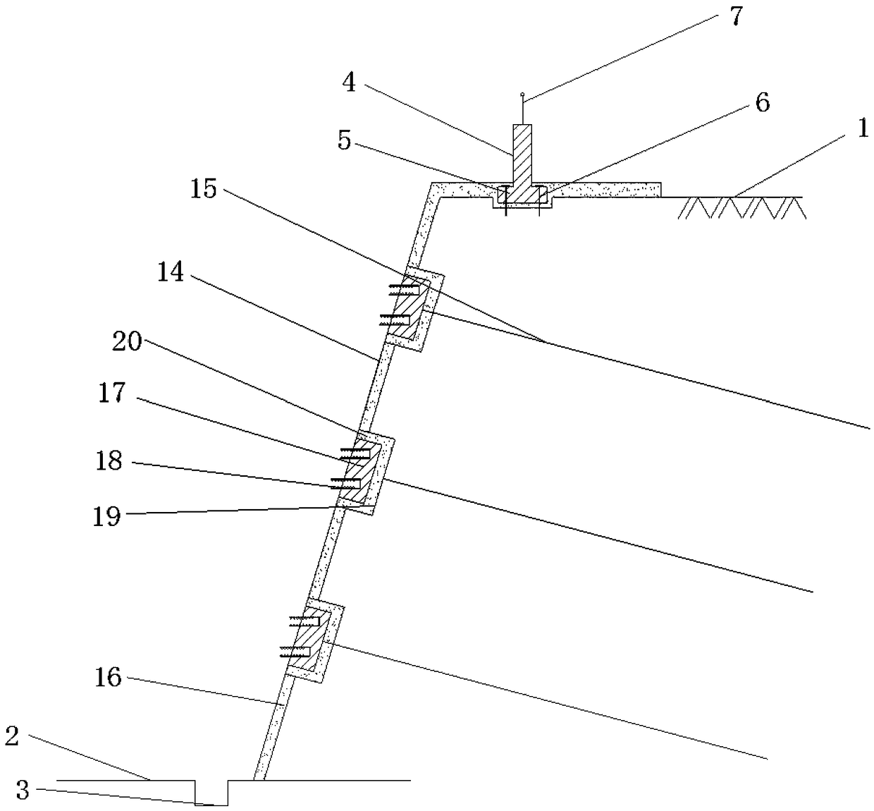
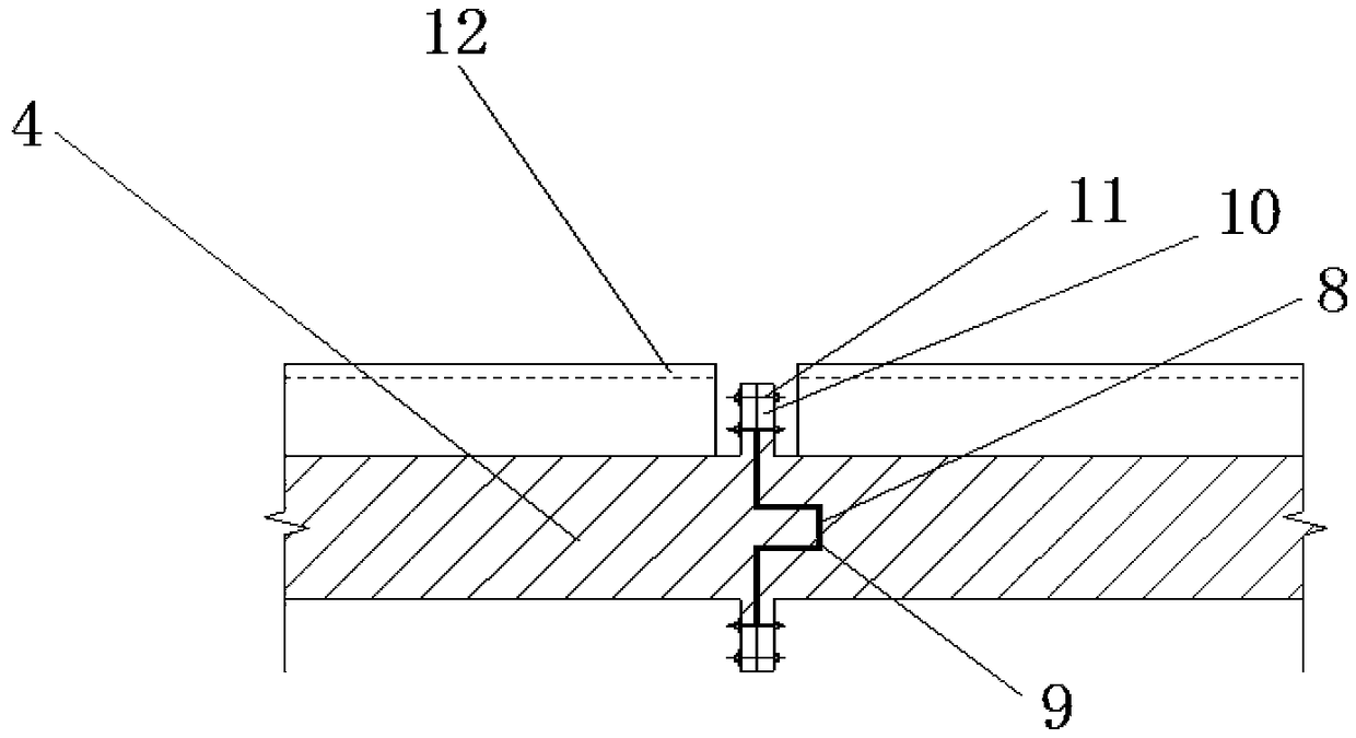
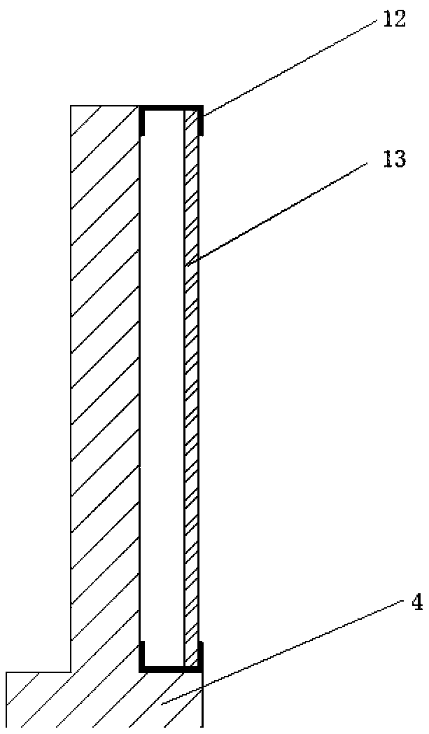
[0052] like Figure 1-4 The cast-in-place integrated pipe gallery includes the foundation trench excavation bottom elevation 2 at the bottom of the foundation pit and the existing ground elevation 1 at the top of the foundation pit; the cast-in-situ comprehensive pipe gallery support formwork is arranged on the foundation trench excavation bottom elevation 2 system and the cast-in-place comprehensive pipe gallery foundation pit support system arranged on both sides of the cast-in-place comprehensive pipe gallery support formwork system, the cast-in-place comprehensive pipe gallery foundation pit support system includes excavation slope 14, excavation slope 14 A number of foundation pit support devices are formed; several foundation pit support devices are equidistantly arranged on the excavation slope 14, and a recycled prefabricated drainage ditch 3 is...


PUM


Abstract

The invention relates to a cast-in-situ comprehensive pipe gallery and a construction method. The cast-in-situ comprehensive pipe gallery comprises a base slot excavation bottom elevation located at the bottom of a foundation trench and an original ground current elevation located at the top of the foundation trench. A cast-in-situ comprehensive pipe gallery formwork system and cast-in-situ comprehensive pipe gallery foundation trench supporting systems located on the two sides of the cast-in-situ comprehensive pipe gallery formwork system are arranged on the base slot excavation bottom elevation. Each cast-in-situ comprehensive pipe gallery foundation trench supporting system comprises an excavation slope, wherein a plurality of foundation trench supporting devices are formed on the excavation slope at equal intervals. A prefabricated drainage ditch which can be used repeatedly is formed in the base slot excavation bottom elevation and is located between the excavation slope and cast-in-situ comprehensive pipe gallery formwork system. According to the cast-in-situ comprehensive pipe gallery and the construction method, a prefabricated retention wall assembled by grooves and tongues is arranged on the top surface of the foundation trench, a channel steel frame is arranged on the outer side of the retention wall, and a propaganda board can be placed in the channel steel frame; and through the structure, the propaganda board can be replaced conveniently, and construction is simple and rapid.

Description

technical field [0001] The invention relates to the technical field of construction of a comprehensive pipe gallery, in particular to a cast-in-place comprehensive pipe gallery and a construction method. Background technique [0002] With the rapid development of my country's economic construction and the increase of urban population, the scale of cities continues to expand, and many cities have problems such as shortage of construction land, road traffic congestion, insufficient urban infrastructure, and increased environmental pollution. The solutions to these problems are as follows: one is to continue to expand the urban extension, and the other is to take the road of connotative development and put the development and utilization of urban underground space on the agenda. The extensional development method relies on expanding the urban land area and extending to high altitudes. On the one hand, the urban population density increases and the urban capacity expands sharply...

Claims


Application Information

Patent Timeline
IPC IPC(8): E02D29/045E02D17/04E02D19/06E03F5/10
CPCE02D17/04E02D19/06E02D29/10E03F5/10
Inventor 王新泉
Owner HANGZHOU JIANGRUN TECH LIMITED
Why Eureka
Try Eureka