Road rainwater pneumatic diversion treatment system and control method thereof

A technology for processing system and rainwater, which is applied in the fields of civil buildings and municipal water supply and drainage, can solve the problem of high cost of electronically controlled hydraulic control, and achieve the effects of mature and reliable price, small amount of excavation and simple construction.

Pending Publication Date: 2019-02-15
WUHAN SHENGYU DRAINING SYST
View PDF9 Cites 3 Cited by
  • Summary
  • Abstract
  • Description
  • Claims
  • Application Information

AI Technical Summary

Problems solved by technology

[0005] In view of the safety problems of electronic control and the high cost of hydraulic control in the prior art, the inventor considered the device using compressed air as the power source

Method used


Image

  • Road rainwater pneumatic diversion treatment system and control method thereof
  • Road rainwater pneumatic diversion treatment system and control method thereof
  • Road rainwater pneumatic diversion treatment system and control method thereof

Examples


Embodiment 1

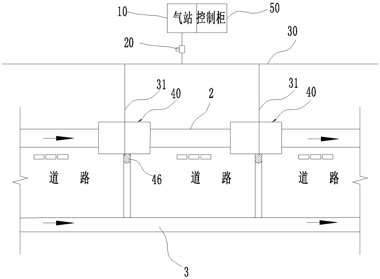
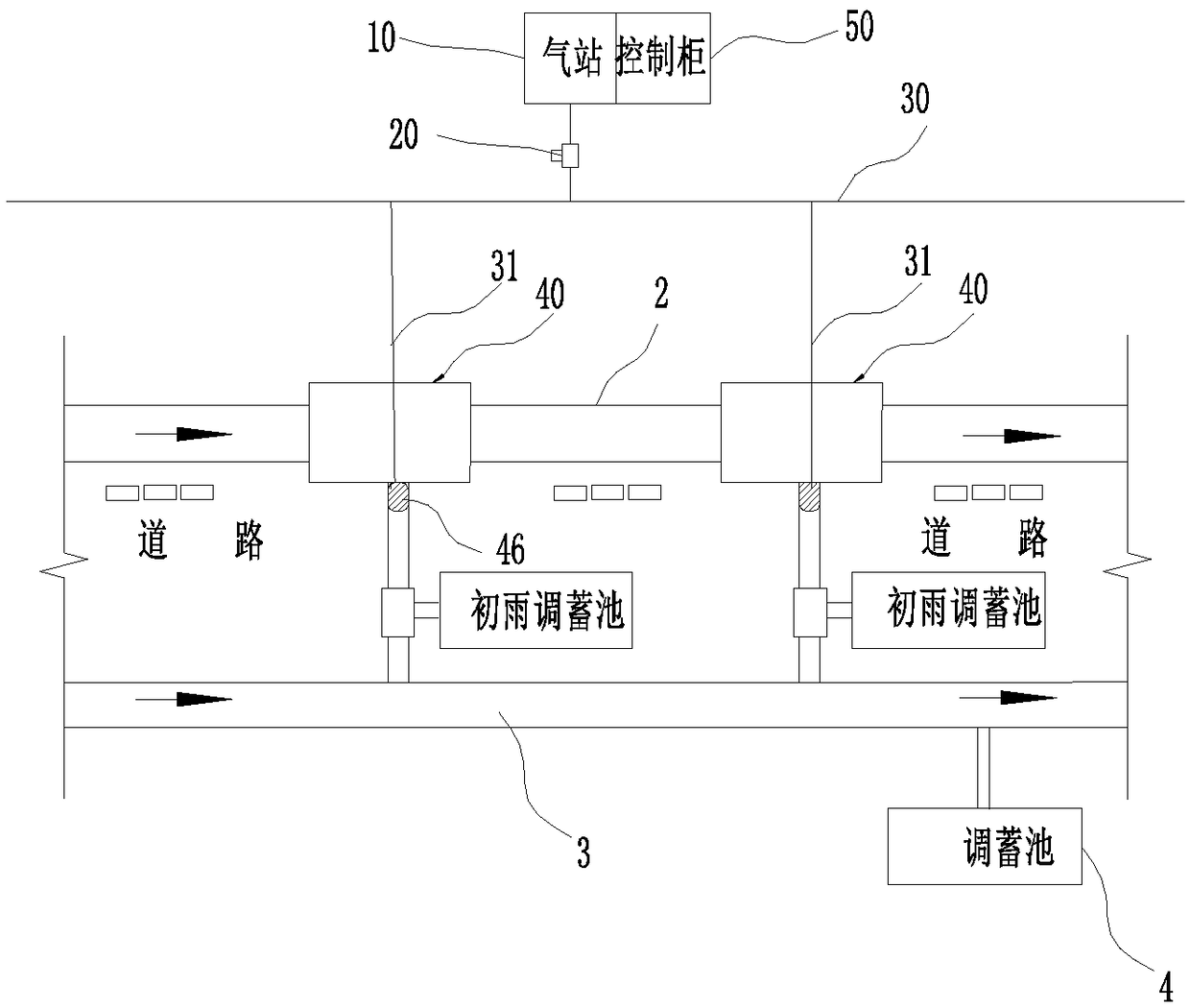
[0072] see figure 1 , figure 2 , image 3 and Figure 4 As shown, the road rainwater pneumatic diversion treatment system is used to divert the fluid in the road municipal rainwater pipe 2, including:

[0073] Compressed gas source 10, used to provide compressed gas;

[0074] Gas delivery pipe, the gas delivery pipeline is used to deliver gas;

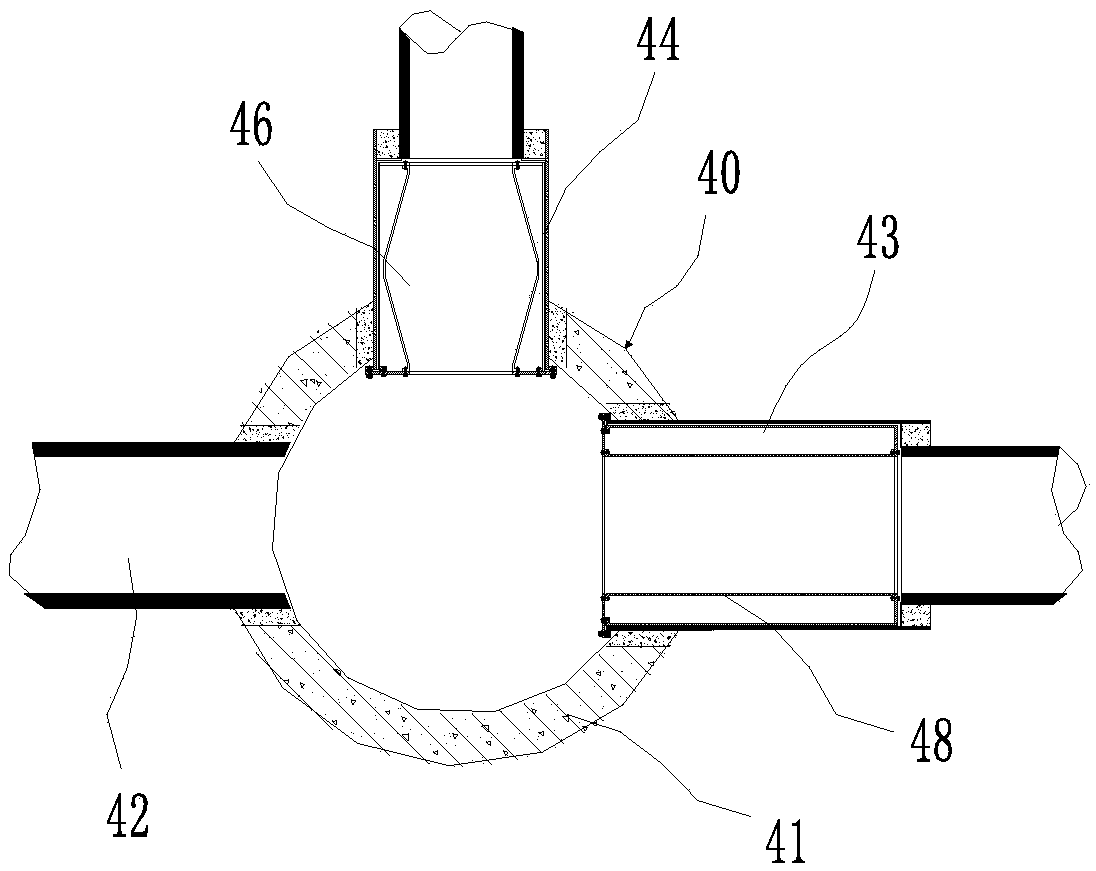
[0075] The diversion well 40 is arranged on the municipal rainwater pipe 2, see image 3 and Figure 4 As shown, the diversion well 40 includes a well body structure 41 and at least an inlet 42 arranged on the well body structure 41, a first water outlet pipe 43, a second water outlet pipe 44 and a pneumatic shut-off device arranged on the second water outlet pipe 44. The second pneumatic shut-off device 46, wherein the inlet 42 is connected to the municipal rainwater pipe 2 upstream of the shunt well 40, the first outlet pipe 43 is connected to the municipal rainwater pipe 2 or natural water body downstream of the shunt well 40...

Embodiment 2

[0081] see Figure 5 As shown, on the basis of Embodiment 1: the system also includes a measuring instrument 60 and a controller 50, the measuring instrument 60 and the control valve 20 are electrically connected to the controller 50 respectively, and the controller 50 controls the valve according to the measurement signal measured by the measuring instrument 60 The control valve 20 operates, wherein,

[0082] When the diversion well 40 is provided with the second pneumatic shut-off device 46, it is the first form:

[0083]The measuring instrument 60 is used to control the second control valve 22 to act separately, so that the second pneumatic shut-off device 46 deflates the second water outlet pipe 44, and diverts the domestic sewage entering the diversion well 40 and / or the initial rainwater to the municipal sewage Pipe 3 or sewage treatment facilities or initial rain pipes or initial rainwater treatment facilities or storage tanks, so that the second pneumatic intercepting...

Embodiment 3

[0107] In this embodiment, on the basis of implementing 1 and 2, at least two diversion wells 40 are arranged at intervals along the municipal rainwater pipe 2, which are respectively diversion wells A and diversion wells B, as an example for illustration, wherein,

[0108] When the diversion well 40 is provided with the second pneumatic shut-off device 46, i.e. form one:

[0109] The gas delivery pipeline includes a second main gas delivery pipe 30 and several gas delivery branch pipes 31, and the second pneumatic shut-off devices 46 of all diversion wells 40 communicate with the second gas delivery main pipe 30 through the gas delivery branch pipes 31 respectively, and the second control valve 22 is set in the second gas delivery main pipe 30, the second control valve 22 is used to control the second pneumatic shut-off device 46 of all diversion wells 40 to inflate or deflate at the same time, the second pneumatic shut-off device 46 of diversion well A passes through diversio...


PUM


Abstract

The invention discloses a road rainwater pneumatic diversion treatment system. The system comprises a compressed air source, a gas delivery pipe, a diversion well arranged on a municipal rainwater pipe and a control valve; the diversion well comprises a well body structure, an inlet, a first water outlet pipe, a second water outlet pipe and a pneumatic cut-off device arranged on the second water outlet pipe, the well body structure is provided with the inlet, the first water outlet pipe and the second water outlet pipe, the pneumatic cut-off device is the second pneumatic cut-off device, the inlet is communicated with the municipal rainwater pipe on the upper stream of the diversion well, the first water outlet pipe is communicated with the municipal rainwater pipe on the lower stream of the diversion well or a natural water body, the second water outlet pipe is communicated with a municipal sewage pipe or sewage treatment facilities, and a third outlet is communicated with a first rain pipe or initial rainwater treatment facilities; the control valve comprises the second control valve which is arranged on the gas delivery pipe, and the second control valve controls charging and discharging of the second pneumatic cut-off device separately, and is used for controlling cut off and conducting of the corresponding second water outlet pipe.

Description

technical field [0001] The invention relates to municipal rainwater and sewage diversion, in particular to a pipeline diversion system and a diversion method, belonging to the technical fields of civil buildings and municipal water supply and drainage. Background technique [0002] At present, in the diversion well, abandonment well and interception well system, the system is composed of water inlet pipe, outlet pipe and sewage pipe, and the domestic sewage in the drainage pipe or the initial rainwater and the later rainwater are diverted. Among them, the domestic sewage or The initial rainwater is intercepted to the sewage pipe and then transported to the sewage treatment plant for treatment and discharged after reaching the standard (further, the initial rainwater can be stored or intercepted to the sewage treatment plant for treatment and discharged after reaching the standard), and the rainwater or mid-late rainwater is directly discharged to natural water bodies middle....

Claims


Application Information

Patent Timeline
Patent Type & Authority Applications(China)
IPC IPC(8): E03F1/00E03F5/10
CPCE03F1/00E03F5/10E03F5/101E03F5/105E03F5/107E03F2201/00
Inventor 周超李习洪
Owner WUHAN SHENGYU DRAINING SYST
Why Eureka
Try Eureka