High-pressure pump for ceramic production

A high-pressure pump and ceramic technology, which is applied to the components of the pumping device for elastic fluids, pumps and pumps for special fluids, etc. problems, to achieve the effect of long maintenance-free period, improved transportation efficiency, and improved pressurization effect

Pending Publication Date: 2019-02-15
佛山市欣科科技有限公司
View PDF6 Cites 0 Cited by
  • Summary
  • Abstract
  • Description
  • Claims
  • Application Information

AI Technical Summary

Problems solved by technology

Because there are a lot of particles mixed in the slurry, when the slurry rotates at high pressure in the pump body, the particles in the slurry are easy to polish the inner wall of the pump body, so that the thickness of the body is gradually thinned, or cracks are formed, which shortens the use of the pump body life
[0004] In addition, when the rotating shaft in the high-pressure pump rotates, it is prone to longitudinal movement, resulting in a gap at the connection between the pump body and the rotating shaft, and the slurry seeps out from the gap, affecting the work of the high-pressure pump and shortening the service life of the high-pressure pump
[0005] Furthermore, since the slurry contains high-hardness particles, the impeller in the high-pressure pump will collide and rub against the particles when it rotates. When the high-speed rotating particles collide with the impeller, the impeller is easy to break, which affects the work of the high-pressure pump.
[0006] In addition, due to the small space in the cavity of the high-pressure pump, the powder production and rotational speed of the high-pressure pump are limited.
[0007] When the ordinary single-suction open impeller high-pressure pump is used in the sizing process, due to pressure fluctuations, the powder-making effect of the spray drying tower is affected, the spraying is not smooth, and the particle size is uneven

Method used


Image

  • High-pressure pump for ceramic production
  • High-pressure pump for ceramic production
  • High-pressure pump for ceramic production

Examples


Embodiment Construction

[0033] In order to make the object, technical solution and advantages of the present invention clearer, the present invention will be further described in detail below in conjunction with the accompanying drawings.

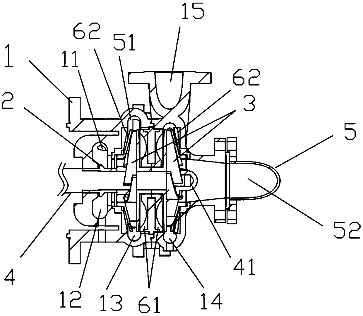
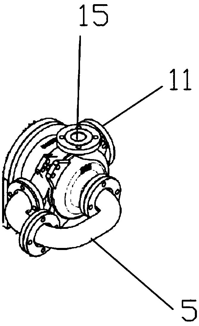
[0034] see figure 1 and figure 2 A high-pressure pump for ceramic production provided by the present invention includes a pump body 1, and the pump body 1 includes a first feed port 11, a first cavity 12 communicated with the first feed port 11, and a first The second cavity 13, the third cavity 14 communicated with the cavity 12, and the first discharge port 15 communicated with the third cavity 14, the crushing wheel 2 arranged in the first cavity 11, respectively arranged in the second The impeller 3 in the cavity 13 and the third cavity 14, the rotating shaft 4 that drives the crushing wheel 2 and the impeller 3 to rotate, and the feed pipe 5 that communicates with the second cavity 13 and the third cavity 14, the slurry flows from the first The feed port 1...


PUM


Abstract

The invention discloses a high-pressure pump for ceramic production. The high-pressure pump includes a pump body, the pump body comprises a first feed port, a first cavity communicating with the firstfeed port, a second cavity communicating with the first cavity, a third cavity, a first discharge hole communicating with the third cavity, a crushing wheel arranged in the first cavity, impellers arranged in the second cavity and the third cavity correspondingly, a rotating shaft driving the crushing wheel and the impellers to rotate, and a feeding pipe communicating with the second cavity and the third cavity, and slurry enters from the first feed port, passes through the first cavity, the second cavity, the feeding pipe and the third cavity successively, and finally the slurry is discharged from the first discharge hole. According to the high-pressure pump for ceramic production, the pressurization effect of the high pressure-pump on the slurry and the transportation efficiency of theslurry are improved.

Description

technical field [0001] The invention relates to the technical field of high-pressure pumps, in particular to a high-pressure pump for ceramic production. Background technique [0002] Ceramics refer to all artificial industrial products that use clay and other inorganic non-metallic minerals as raw materials. It includes various products made of clay or a mixture containing clay through mixing, forming, and calcination. Divided into mud slurry, high-level slurry tank, grouting, molding, ceramic sheet cutting, belt mold drying, billeting, body transfer and drying, soup glaze, external water replenishment, glaze dipping, dust sweeping inspection, boxing, Firing, etc., the production of ceramics can be used as handicrafts or as materials for building houses, and its market demand has always been high. [0003] After the mud is slurried, it needs to go through a high-pressure pump to feed the slurry and mix it evenly again, and then transport the slurry to the spray drying towe...

Claims


Application Information

Patent Timeline
Patent Type & Authority Applications(China)
IPC IPC(8): F04D7/04F04D29/22F04D29/02F04D29/42
CPCF04D7/045F04D29/026F04D29/185F04D29/2288F04D29/426F05D2300/2261
Inventor 杨志
Owner 佛山市欣科科技有限公司
Why Eureka
Try Eureka