
Shock absorber capable of prolonging service life

A shock absorber, life-span technology, used in shock absorbers, springs/shock absorbers, shock absorbers, etc., can solve problems such as reducing the service life of the guide, damage to the guide, and rupture of the limit block of the shock absorber. Achieve the effect of reducing wear and prolonging service life

Active Publication Date: 2019-02-15
嘉兴市富莱德汽车零部件制造有限公司
View PDF9 Cites 0 Cited by
  • Summary
  • Abstract
  • Description
  • Claims
  • Application Information

AI Technical Summary

Problems solved by technology

[0004] In order to realize the limit of the piston rod in the existing shock absorbers, there are usually two forms. One is to set a limit block on the piston rod. Most of the vehicle shock absorber limit blocks are cylindrical rubber parts. It is a simple straight wall state, so if the hardness is set too high, there will be a sharp collision noise when hitting the limit, if the hardness is set too low, the displacement will be too large when the limit is reached, and the limit block of the shock absorber will be very large. It is easy to break at the straight wall of the waist; the other is to realize the limit through the hard collision between the piston and the guide, which will cause great damage to the guide and reduce the service life of the guide

Method used


Image

  • Shock absorber capable of prolonging service life
  • Shock absorber capable of prolonging service life
  • Shock absorber capable of prolonging service life

Examples


Embodiment 1

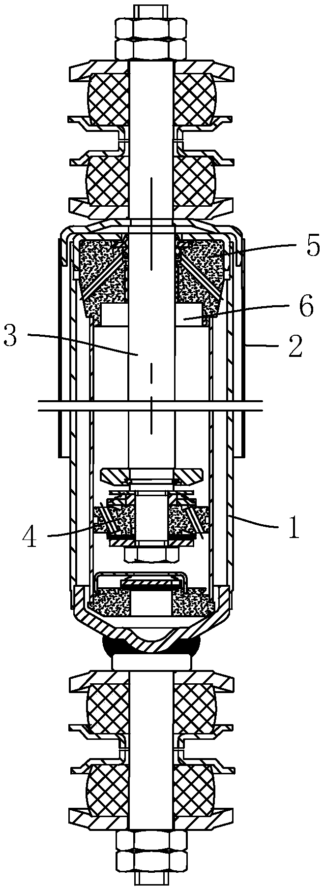
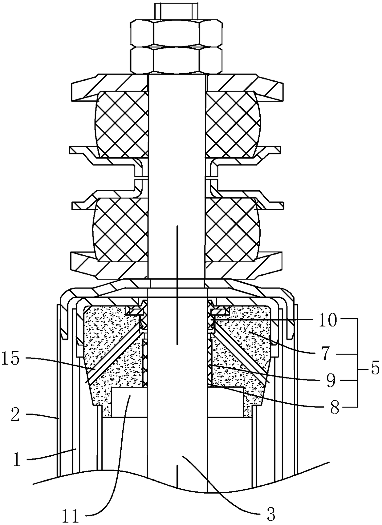
[0034] refer to figure 1 and figure 2, is a shock absorber that can prolong the service life disclosed by the present invention, comprising an oil storage tube 1, a dust cover 2 covering one end of the oil storage tube 1, passing through the end of the oil storage tube 1 and fixedly connected to the The piston rod 3 in the middle of the dust cover 2, the end of the piston rod 3 extending into the oil storage tube 1 is connected to the piston 4, and the oil storage tube 1 is fixed at the end near the dust cover 2 and located inside the oil storage tube 1. The guide assembly 5, the end of the guide assembly 5 facing the piston 4 is provided with a hydraulic limit assembly 6; when the shock absorber is working, the piston rod 3 slides up and down relative to the oil storage cylinder 1, when the piston rod 3 drives the piston 4 toward When the direction of the guide assembly 5 moves close, the piston rod 3 is hydraulically limited by the hydraulic limit assembly 6, avoiding the ...

Embodiment 2

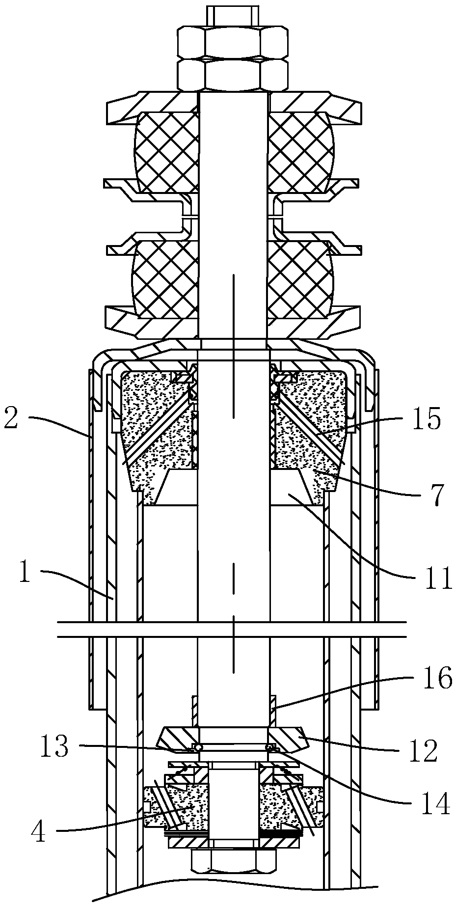
[0040] refer to image 3 , is a shock absorber that can prolong the service life disclosed by the present invention. The difference from Embodiment 1 is that the buffer tank 11 is in the shape of a truncated cone, and the diameter of the buffer tank 11 gradually becomes smaller from the outside to the inside, that is, from close to The diameter of one end of the locking ring 12 gradually decreases toward the end away from the locking ring 12, the shape of the locking ring 12 is adapted to the buffer groove 11, and the gap between the locking ring 12 and the buffer groove 11 is 0.1 mm.

[0041] The piston rod 3 drives the locking ring 12 to move toward the guide 7. When the locking ring 12 enters the buffer tank 11, the end of the locking ring 12 with a smaller diameter enters the end of the buffer tank 11 with a larger diameter. At this time, the oil The resistance to the locking ring 12 is small. As the locking ring 12 continues to move, the gap between the side wall of the l...

Embodiment 3

[0044] refer to Figure 4 , is a shock absorber that can prolong the service life disclosed in the present invention. The difference from Embodiment 1 is that the side wall of the buffer tank 11 is arranged in a stepped shape, and the side wall of the locking ring 12 is in a shape that matches the buffer tank 11. It is arranged in a stepped shape, and the gap between the locking ring 12 and the inner wall of the buffer groove 11 is 0.1mm.

[0045] When the piston rod 3 drives the locking ring 12 to move toward the guide 7, the gap formed between the side wall of the locking ring 12 and the inner wall of the buffer tank 11 is also stepped, and compared with the gap in the first embodiment, the oil flow rate is lower. The resistance is greater, and the stepped shape has a bent part. When the bent part of the locking ring 12 abuts against the bent part of the inner wall of the buffer groove 11, it is easier to form a sealed environment, so that the locking ring 12 and the guide ...


PUM


Abstract

The invention discloses a shock absorber capable of prolonging the service life, relates to the field of car shock absorbers, and aims to solve the problem that a conventional shocker absorber capableof being limited is short in service life. According to the technical scheme, the key point is that the shock absorber comprises an oil storage barrel, a dustproof cover which covers one end of the oil storage barrel, a piston rod which is arranged on the end part of the oil storage barrel in a penetrating mode and is fixedly connected to the middle part of the dustproof cover, wherein one end, extending into the oil storage barrel, of the piston rod is connected with a piston; a guide assembly is fixedly arranged inside the end part, close to the dustproof cover, of the oil storage barrel; and one end, towards the piston, of the guide assembly is equipped with a hydraulic limiting assembly. According to the shock absorber capable of prolonging the service life disclosed by the invention,conventional hard collision is changed into hydraulic limiting; a nearly sealed cavity is formed between a locking ring and a guider, so that hydraulic limiting on the locking ring is realized by utilizing oil pressure in the cavity, and hard collision on the guider is reduced, and therefore, the service life of the shock absorber is effectively prolonged.

Description

technical field [0001] The invention relates to the technical field of shock absorbers, in particular to a shock absorber with extended service life. Background technique [0002] When the car passes through uneven roads, although the shock-absorbing spring in the shock absorber system can filter the vibration of the road surface, the spring itself will reciprocate, and the shock absorber is used to suppress the reciprocating jump of the spring. The structure of the shock absorber is that the piston rod with the piston is inserted into the barrel, the barrel is filled with oil, and the piston has an orifice, so that the oil in the two spaces separated by the piston can complement each other. [0003] The working principle of the shock absorber is that when there is relative movement between the frame and the axle or between the vehicle body and the axle, the piston in the shock absorber moves up and down, and the oil in the shock absorber cavity passes through one cavity rep...

Claims


Application Information

Patent Timeline
Patent Type & Authority Applications(China)
IPC IPC(8): F16F9/19F16F9/32F16F9/36F16F9/38
CPCF16F9/19F16F9/3207F16F9/3214F16F9/36F16F9/38
Inventor 金法根
Owner 嘉兴市富莱德汽车零部件制造有限公司
Learn More