
Quartz resonant current sensor

A current sensor and resonant technology, applied in the field of current sensors using high-Q quartz crystal resonators, can solve the problems of affecting measurement bandwidth, affecting measurement accuracy, and low sensitivity, and achieve the effect of simple driving circuit and detection circuit

Active Publication Date: 2019-02-15
NANJING UNIV OF SCI & TECH
View PDF4 Cites 3 Cited by
  • Summary
  • Abstract
  • Description
  • Claims
  • Application Information

AI Technical Summary

Problems solved by technology

For the Rogowski coil, the position of the primary current affects the measurement accuracy. Due to the low sensitivity, it is not suitable for measuring small currents. The distributed capacitance of the secondary coil will affect the measurement bandwidth.

Method used


Image

  • Quartz resonant current sensor
  • Quartz resonant current sensor
  • Quartz resonant current sensor

Examples


Embodiment

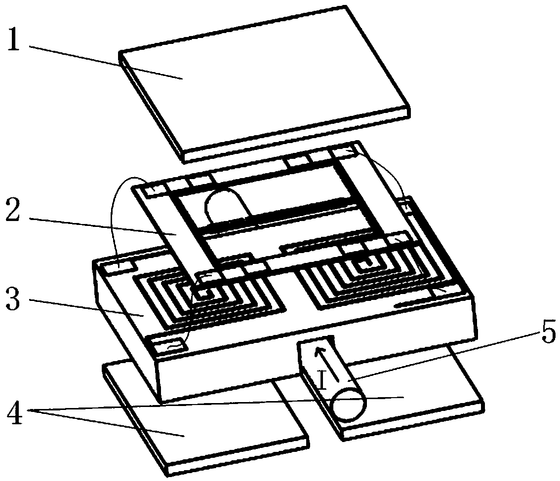
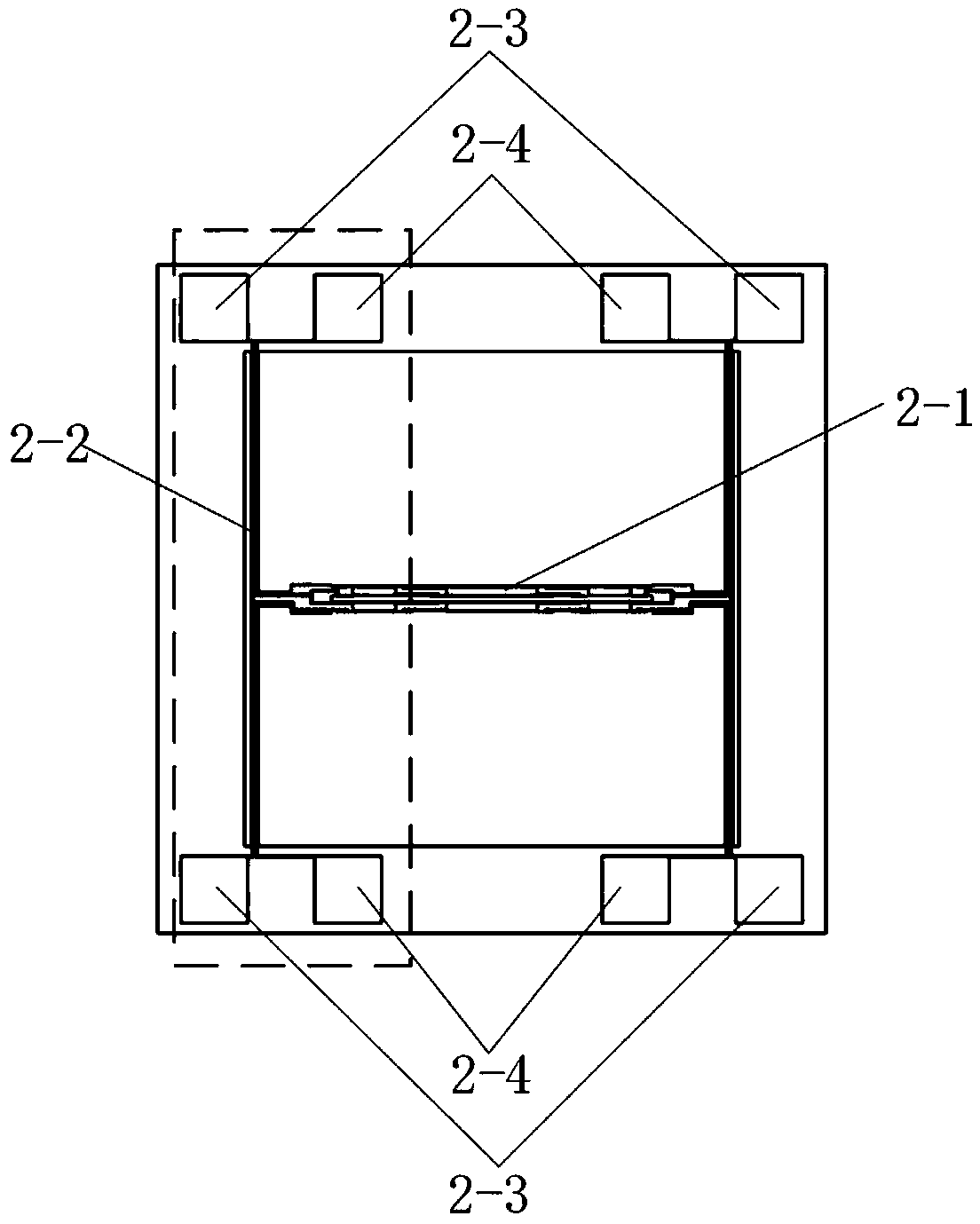
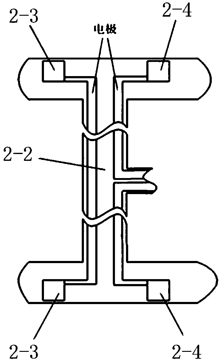
[0027] Such as figure 1 As shown, the quartz resonant current sensor shown in this embodiment includes a permanent magnet 1, a resonant current sensing unit 2, a PCB board with an induction coil 3, and a permanent magnet 4, wherein 5 is a current wire to be measured. The resonant current sensing unit 2 is an integrated structure made of a high-Q quartz crystal, such as figure 2 As shown, it includes a quartz tuning fork 2-1 fixed at both ends, a current-carrying elastic support beam 2-2, a current input pad 2-3 and a tuning fork excitation pad 2-4.

[0028] The quartz tuning fork 2-1 includes two vibrating beams with the same size and parallel to each other. Both ends of the quartz tuning fork 2-1 are respectively fixed in the middle of two current-carrying elastic support beams 2-2, and the length direction of the quartz tuning fork 2-1 is perpendicular to the length direction of the current-carrying elastic support beams 2-2, and the current-carrying elastic Both ends of ...


PUM


Abstract

The invention relates to a quartz resonant current sensor. A current sensitive unit includes a quartz tuning fork fixed at both ends and current-carrying elastic support beams. The two ends of the quartz tuning fork are respectively fixed to the middles of the two current-carrying elastic support beams, and the length direction of the quartz tuning fork is perpendicular to the length direction ofthe current-carrying elastic support beams. The surfaces of the current-carrying elastic support beams are plated with electrodes along the axes, and the two ends of the electrodes are respectively connected with the two ends of corresponding induction coils. The two ends of the current-carrying elastic support beams are arranged on a peripheral frame. When a current under test changes, the two induction coils produce induction currents which are of the same magnitude and are opposite in direction. The induction currents flow through the two current-carrying elastic support beams along the electrodes respectively. The current-carrying elastic support beams generate an ampere force under the action of a magnetic field provided by a permanent magnet in order to make the quartz tuning fork stressed axially and change the resonance frequency of the tuning fork. The current can be detected according to the frequency variation of the quartz tuning fork. The quartz resonant current sensor hasthe advantages of low loss, high sensitivity and small size.

Description

technical field [0001] The invention belongs to a quartz resonant current sensor, in particular to a current sensor using a high-Q quartz crystal resonator. Background technique [0002] As a basic physical quantity, electric current is of great significance to its precise measurement. There are many common current sensors. One type is a shunt based on Ohm's law, but the shunt is connected in series in the circuit, which has its development limitations, mainly because the loss is large when measuring a large current. The other type of current sensor is based on The Ampere loop theorem indirectly measures the magnitude and direction of the current by measuring the magnetic field, mainly represented by Hall current sensors, fluxgate current sensors, magnetoresistive current sensors, Rogowski coils, and current transformers. These current sensors have more or less application limitations, such as Hall sensors, high-frequency alternating current will cause the core to overheat....

Claims


Application Information

Patent Timeline
IPC IPC(8): G01R19/00G01R33/038
CPCG01R19/0092G01R33/038
Inventor 李大威卞雷祥朱志伟贾云飞
Owner NANJING UNIV OF SCI & TECH
Learn More