
An optical fiber light-emitting structure, a liquid medicine dotting processing method, and a medicine dotting device

A technology of light-emitting structure and processing method, which is applied in the direction of bundled optical fibers, etc., to achieve the effect of increasing the scope of application, no starting current impact, and improving the use effect

Active Publication Date: 2020-03-31
广州锐亚格电子有限公司
View PDF7 Cites 0 Cited by
  • Summary
  • Abstract
  • Description
  • Claims
  • Application Information

AI Technical Summary

Problems solved by technology

[0003] The purpose of making optical fibers is to transmit light signals, so enterprises and researchers in this field have formed inertial thinking, and have not thought of directly using the light and thin characteristics of optical fibers to make them into luminous lighting products

Method used


Image

  • An optical fiber light-emitting structure, a liquid medicine dotting processing method, and a medicine dotting device
  • An optical fiber light-emitting structure, a liquid medicine dotting processing method, and a medicine dotting device
  • An optical fiber light-emitting structure, a liquid medicine dotting processing method, and a medicine dotting device

Examples


Embodiment 1

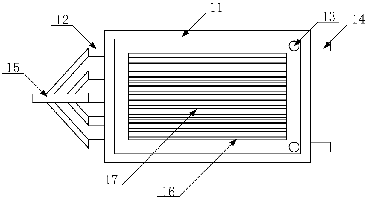
[0036] Such as figure 1 , 2 As shown, an optical fiber light-emitting structure includes a reflective sheet 1, an optical fiber layer arranged on the reflective sheet 1, a light source connected to the optical fiber layer, a small hole arranged on the upper side of the optical fiber layer, and an optical fiber layer arranged on the optical fiber layer and the reflective sheet 1. The bottom layer of transparent glue layer 6 between them, and the top layer of transparent glue layer 7 arranged on the upper side of the optical fiber layer; The surface is fixed on the reflective sheet 1, and the end of the leading line is connected to the light source; the small hole is formed after stripping the coating layer of the optical fiber, and the small hole is set against the reflective sheet 1.

[0037] When in use, the light from the light source is transmitted through the optical fiber, and when the light is transmitted to the position where the small hole is opened on the optical fib...

Embodiment 2

[0047] A method for processing liquid crystals of optical fiber light-emitting structures, comprising the following steps:

[0048] (1) Cut the reflector according to the requirement;

[0049] The shape of the reflective sheet is not limited, and specific shapes such as rectangle, circle, ellipse, polygon, star, and heart can be adjusted according to requirements. The reflective sheet can provide a certain support for the optical fiber, reduce the difficulty of installing the optical fiber, and has a certain degree of toughness, which can be bent within a certain range, so that it can fit well on the surface of different objects and improve the scope of application of the product .

[0050] (2) smear transparent glue on the upper surface of the reflective sheet and fix the optical fiber wiring on the reflective sheet through the transparent glue, and then make the transparent glue solidify into the bottom transparent glue layer by natural ventilation or low-temperature drying...

Embodiment 3

[0061] The only difference between this example and Example 2 is that the heating temperature of the low-temperature drying described in step (2), step (3) and step (5) is 85°C.


PUM

PropertyMeasurementUnit
diameteraaaaaaaaaa

Abstract

The invention discloses an optical fiber luminescent structure, which comprises a reflector, an optical fiber layer on the reflector, a light source connected with the optical fiber layer, a hole on the upper side of the optical fiber layer, a bottom transparent glue layer between the optical fiber layer and the reflector, and a top transparent glue layer on the upper side of the optical fiber layer. The fiber layer comprises several fibers, and the front segment is luminescent surface while the rear segment is light inducer. The luminescent surface of the fiber is fixed on the reflector, andthe end of the light inducer is connected with the light source. The invention also discloses a pouring processing method and a pouring device with optical fiber luminescent structure. The luminescentstructure has the features of homogeneous emission, lower energy consumption, larger coverage, and lighter weight. The device is convenient, safe and reliable, and it makes the processing much simpler and improves the processing efficiency further.

Description

technical field [0001] The invention belongs to the field of lighting, and specifically refers to an optical fiber light-emitting structure, a liquid medicine dotting processing method, and a medicine dotting device. Background technique [0002] The optical fiber is composed of two layers of glass with different refractive indices. The inner layer is the optical core with a diameter of several microns to tens of microns, and the outer layer has a diameter of 0.1 to 0.2 mm. Generally, the refractive index of the inner core glass is 1% larger than that of the outer glass. The outermost structure of the optical fiber is the coating layer. When the glass optical fiber is pulled out from the preform rod, in order to prevent contamination by dust, a layer of elastic coating is cured with ultraviolet light; it is made of acrylate, silicone rubber and Composed of nylon etc. [0003] The purpose of making optical fibers is to transmit light signals, so enterprises and researchers ...

Claims


Application Information

Patent Timeline
Patent Type & Authority Patents(China)
IPC IPC(8): G02B6/04
CPCG02B6/04
Inventor 黄利军汪毅忠李娜
Owner 广州锐亚格电子有限公司
Learn More