Workshop dry-type transformer cooling device
A dry-type transformer and cooling device technology, applied in the field of transformers, can solve the problems of slow heat dissipation of coils, and achieve the effects of energy saving, rapid heat dissipation, and accelerated heat dissipation
- Summary
- Abstract
- Description
- Claims
- Application Information
AI Technical Summary
Problems solved by technology
Method used
Image

Examples
Embodiment 1
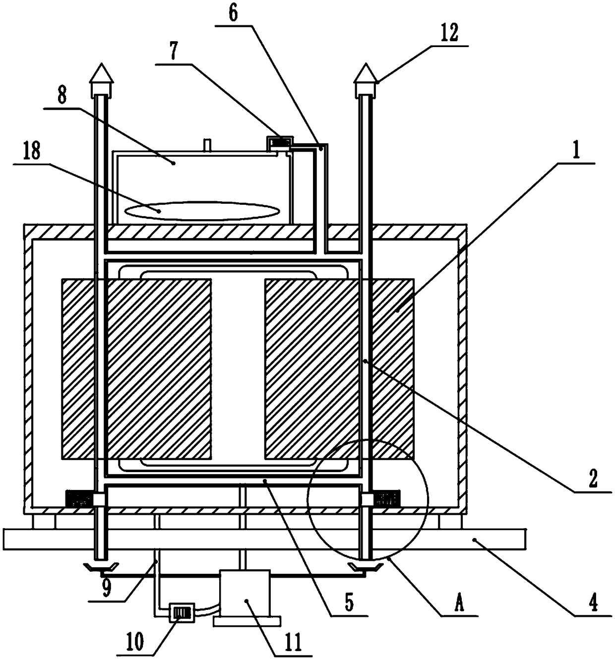
[0051] A workshop dry-type transformer cooling device, including a rectangular base 4, a housing and several coil groups inside the housing; in this embodiment, the number of coil groups is 2, arranged in the horizontal direction.
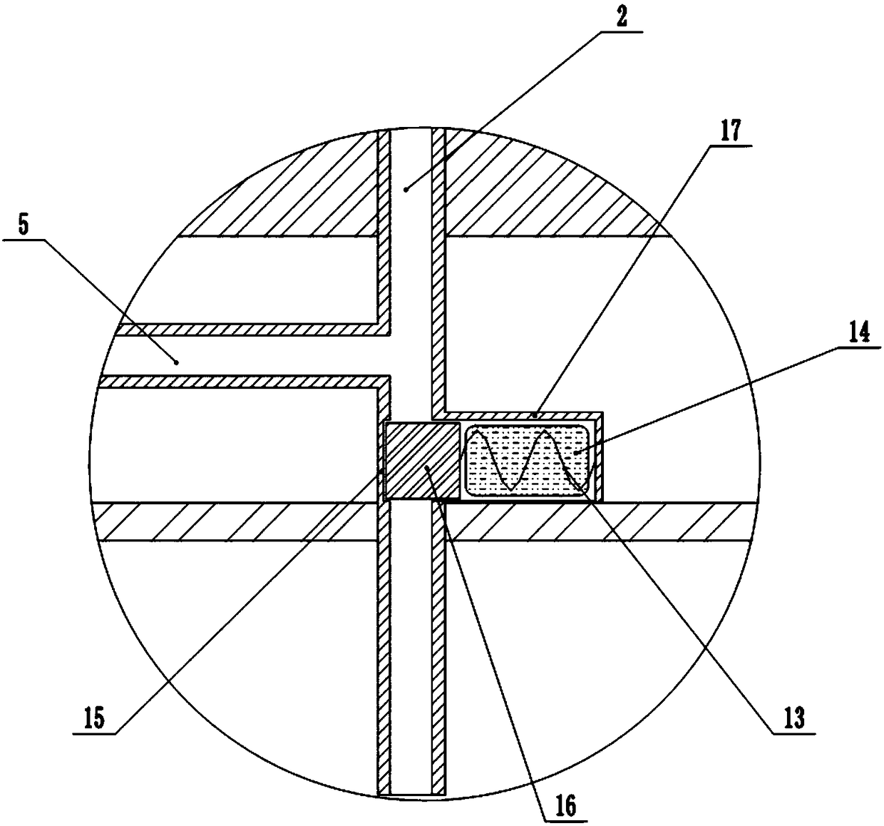
[0052] The coil group includes a coil 1 and a central pipe 2; the coil 1 is made of flat copper wire; the coil 1 is coaxially arranged in multiple sections and wound around the central pipe 2; two adjacent sections of the fired coil 1 are separated by a mesh pad; the central The pipe 2 is closely attached to the coil 1; the coil 1, the grid pad and the central pipe 2 are poured into one body by epoxy resin.
[0053] Such as figure 1 As shown, the central pipe 2 is hollow, and the upper end and the top and lower ends are open; the upper end and the lower end of the central pipe 2 extend out of the transformer shell, and the upper end of the central pipe 2 is welded with a conical waterproof cover 12, between the central pipes 2 of the adjacent coil ...
Embodiment 2
[0074] The difference from Embodiment 1 is that a collection bucket is provided below the lower end of the central pipeline, and the bottom of the collection bucket is connected to the auxiliary oil tank through a conduit.
[0075] After the collection bucket is set, it is convenient to recover the oil leaked from the bottom of the central pipeline to avoid oil waste.
Embodiment 3
[0077] The difference with Embodiment 2 is that a second pressure sensor is also provided at the bottom of the fuel tank 8, and the second pressure sensor is connected to the signal of the single-chip microcomputer; when the single-chip microcomputer judges that the weight signal of the first pressure sensor exceeds the first threshold and the weight signal of the second pressure sensor When it is lower than the second threshold, the single-chip microcomputer starts the oil pump 10 through the driver.
[0078] When the weight signal of the second pressure sensor is lower than the second threshold, it shows that the oil tank 8 has less oil, and now the oil pump 10 is started to withdraw the oil, which can replenish the oil in the oil tank 8 to prevent too little oil.
PUM
 Abstract
Description
Claims
Application Information
 - R&D
- Intellectual Property
- Life Sciences
- Materials
- Tech Scout
- Unparalleled Data Quality
- Higher Quality Content
- 60% Fewer Hallucinations
Browse by: Latest US Patents, China's latest patents, Technical Efficacy Thesaurus, Application Domain, Technology Topic, Popular Technical Reports.
© 2025 PatSnap. All rights reserved.Legal|Privacy policy|Modern Slavery Act Transparency Statement|Sitemap|About US| Contact US: help@patsnap.com