Three-dimensional high-energy electronic imaging system and method

A high-energy electronic and imaging system technology, applied in circuits, discharge tubes, electrical components, etc., can solve problems such as inability to present three-dimensional imaging and inability to fully grasp the internal information of the target.

Inactive Publication Date: 2019-02-15
INST OF MODERN PHYSICS CHINESE ACADEMY OF SCI
View PDF1 Cites 2 Cited by
  • Summary
  • Abstract
  • Description
  • Claims
  • Application Information

AI Technical Summary

Problems solved by technology

[0004] The current high-energy electron imaging technology is two-dimensional imaging, which can only display the plane information of the target, but cannot present a complete three-dimensional imaging, resulting in the inability to fully grasp the internal information of the target during the experiment

Method used


Image

  • Three-dimensional high-energy electronic imaging system and method
  • Three-dimensional high-energy electronic imaging system and method
  • Three-dimensional high-energy electronic imaging system and method

Examples


Embodiment Construction

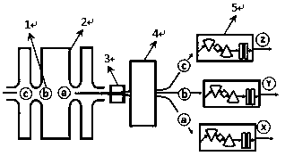
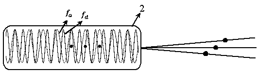
[0017] Such as Figure 1~3 As shown, a three-dimensional high-energy electron imaging system includes a high-energy linac that produces three continuous electron beams 1, a deflection chamber 2 connected to the high-energy linac, a cutting magnet 4, and a non-dispersive beam transport line 5 , target target 6 and imaging magnet lens system 7.

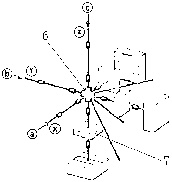
[0018] A field-free drift section 3 is provided between the deflection chamber 2 and the cutting magnet 4; a non-dispersive beam transport line 5 is provided on the side of the cutting magnet 4 opposite to the field-free drift section 3, and the non-dispersive beam transport line 5 A target 6 is provided at the end of the target 5; an imaging magnet lens system 7 is provided on the three orthogonal directions X, Y, and Z of the target 6.

[0019] Wherein: the deflection cavity 2 is matched with the high-energy linear accelerator.

[0020] An imaging method of a three-dimensional high-energy electron imaging system refers to: first, th...


PUM


Abstract

The invention relates to a three-dimensional high-energy electronic imaging system. The system comprises a high-energy linear accelerator for generating three continuous electron beam bunches, and a deflection cavity connected with the high-energy linear accelerator, a cutting magnet, a dispersion-free beam transport line, a target and an imaging magnet lens system; a non-field drift section is arranged between the deflection cavity and the cutting magnet; the dispersion-free beam transport line is arranged on one side, opposite to the non-field drift section, of the cutting magnet; the targetis arranged at the tail end of the dispersion-free beam transport line; and the imaging magnet lens system is arranged in three orthogonal directions of X, Y and Z of the target separately. By virtueof the three-dimensional high-energy electronic imaging system, three-dimensional imaging can be realized, the problem that the existing imaging technology can only achieve two-dimensional imaging and cannot completely reflect all information of the target is effectively solved, and the development of related researches such as high-energy electronic imaging, high-energy density physical and inertial confinement fusion and the like promoted.

Description

technical field [0001] The invention relates to an imaging method, in particular to a three-dimensional high-energy electronic imaging system and method. Background technique [0002] Energy is the material basis of human activities, and the development of human society is inseparable from the utilization of energy. Fossil energy represented by traditional coal, oil, and natural gas has limited resources and will cause serious environmental pollution during use. Therefore, actively looking for clean and safe new energy has become an inevitable choice in today's world. Controlled thermonuclear fusion reaction can release huge energy. This energy is clean, safe, and uses inexhaustible seawater as raw material. Therefore, controlled thermonuclear fusion energy is the main hope of new energy for human beings in the future. Inertial confinement nuclear fusion is one of the most likely ways to achieve controlled thermonuclear fusion. The inertial confinement fusion capsule is in...

Claims


Application Information

Patent Timeline
Patent Type & Authority Applications(China)
IPC IPC(8): H01J37/22G06T1/00G06T3/00
CPCG06T1/0007G06T3/00H01J37/222
Inventor 申晓康张子民曹树春赵全堂宗阳刘铭李中平肖荣庆
Owner INST OF MODERN PHYSICS CHINESE ACADEMY OF SCI
Why Eureka
Try Eureka