Lithium battery module based on pulsating heat pipe radiation

A technology of pulsating heat pipes and lithium batteries, which is applied to secondary batteries, circuits, electrical components, etc., can solve the problems of difficult processing of evaporation section and condensation section, poor heat dissipation effect, and poor heat transfer effect, so as to improve the response to the environment Ability to change ambient temperature, light weight, good sealing effect

Inactive Publication Date: 2019-02-15
JIANGSU UNIV
View PDF9 Cites 2 Cited by
  • Summary
  • Abstract
  • Description
  • Claims
  • Application Information

AI Technical Summary

Problems solved by technology

The invention patent with the patent publication number CN102157761A discloses a power battery thermal management system based on pulsating heat pipes. The pulsating heat pipes are distributed on the surface of the battery cells in a row-like manner of bending back and forth, which is difficult to process; the evaporation section of the heat pipes The heat-conducting adhesive is bonded to the surface of the battery cell, the contact area is small, and the thermal resistance is large; when it relies on the gas when the car is running to dissipate heat from the condensing end, the arrangement of the condensing end makes the windward area smaller and the heat dissipation effect Poor; when it mainly relies on external liquid or solid phase change materials for heat dissipation, higher requirements are placed on the sealing of the device
The utility model patent with the patent announcement number CN202150527U proposes a power battery cooling device based on a separate pulsating heat pipe. In order to realize the variable relative position of the evaporation section and the condensation section, there are difficulties in specific processing
Similarly, the contact between the heat pipe and the battery cell is in the form of line contact, and the heat transfer effect is not good.

Method used


Image

  • Lithium battery module based on pulsating heat pipe radiation
  • Lithium battery module based on pulsating heat pipe radiation
  • Lithium battery module based on pulsating heat pipe radiation

Examples


Embodiment Construction

[0027] The present invention will be further described below in conjunction with the accompanying drawings and specific embodiments, but the protection scope of the present invention is not limited thereto.

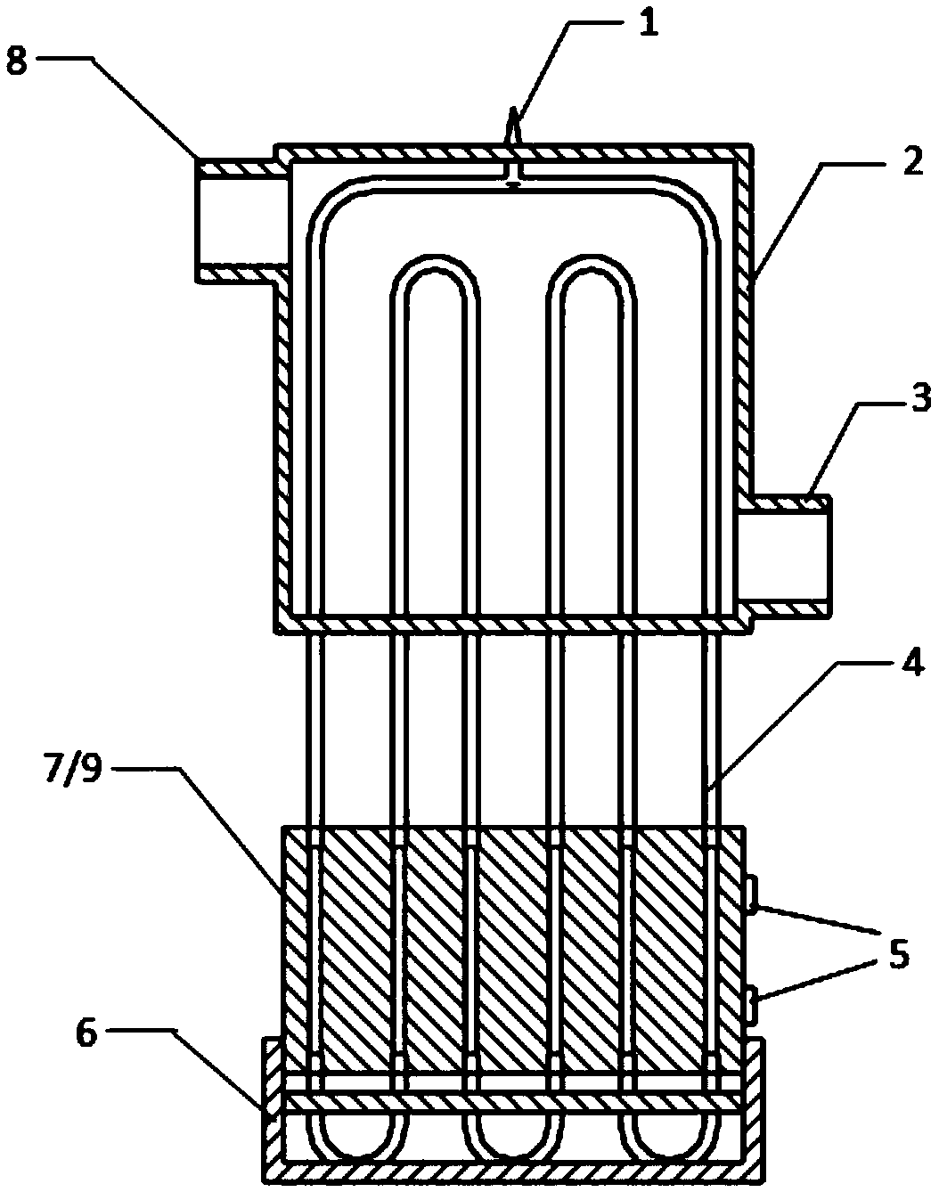
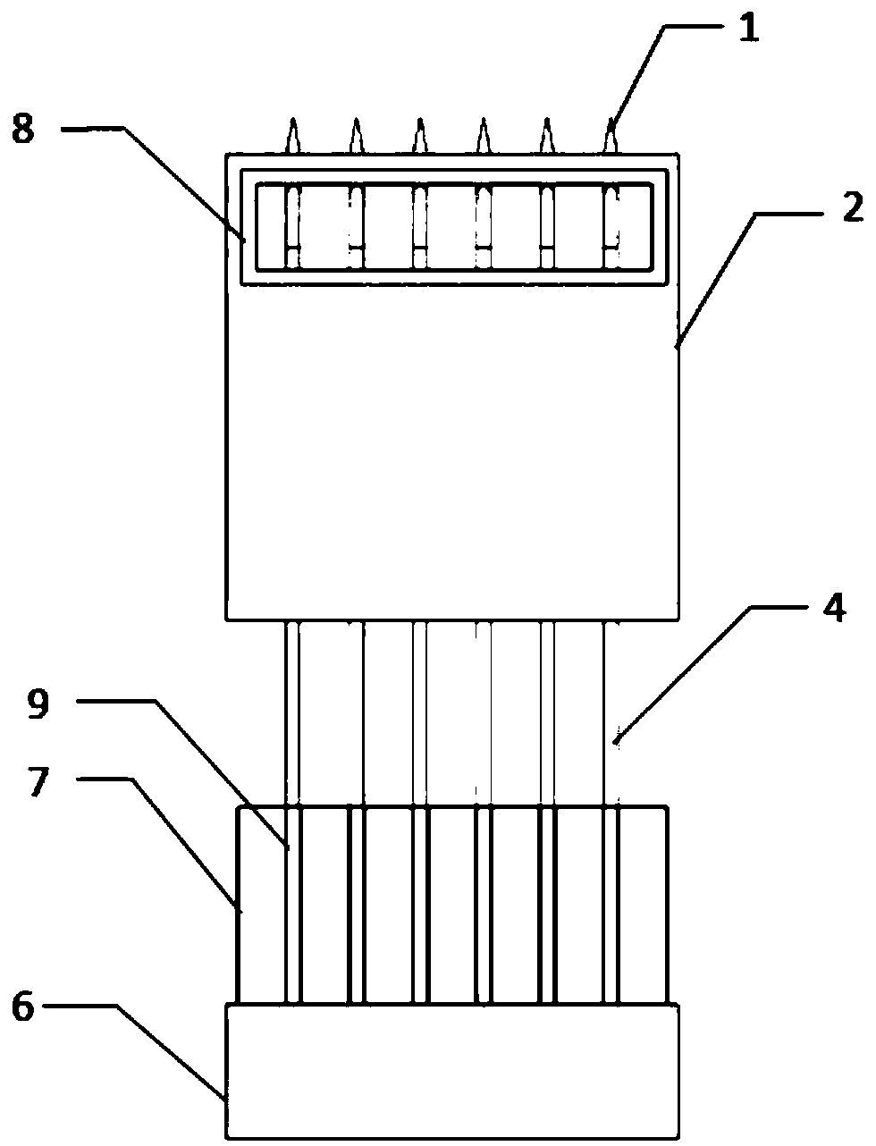
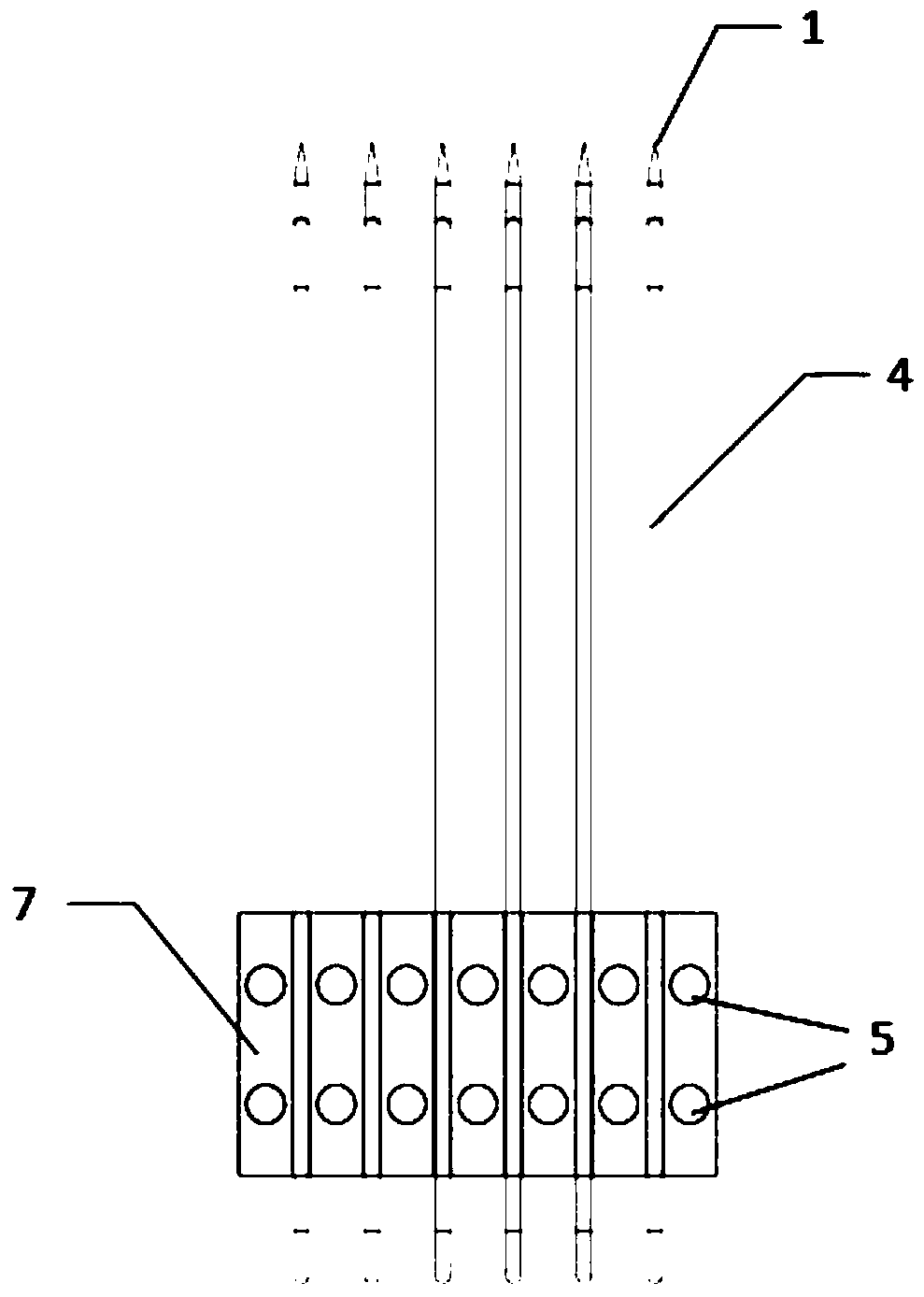
[0028] Such as figure 1 and figure 2 As shown, the lithium battery module based on the pulsating heat pipe heat dissipation of the present invention includes several battery cells 7, pulsating heat pipes 4, metal plates 9 and a condensation section box 2, and metal cells are fixed between adjacent battery cells 7. plate 9, the inside of the metal plate 9 is provided with an evaporation channel, and the metal plate 9 is externally connected to the pulsating heat pipe 4, and the pulsating heat pipe 4 and the evaporation channel form a closed-loop pipeline; several of the pulsating heat pipes 4 are provided with condensation The section box 2 is used to cool down the pulsating heat pipe 4; the pulsating heat pipe 4 is filled with a working medium, and the working medium is...


PUM


Abstract

The invention provides a lithium battery module based on pulsating heat pipe radiation. The lithium battery module comprises a plurality of battery units, pulsating heat pipes, metal plates and a condensing section box, wherein the metal plates are fixed between the adjacent battery units; evaporating flow passages are formed in the metal plates; the metal plate are externally connected with the pulsating heat pipes; the pulsating heat pipes and the evaporating flow passages form a closed-loop pipeline; the condensing section box is arranged outside a plurality of the pulsating heat pipes; thepulsating heat pipes are filled with a working medium; the evaporating flow passages are U-shaped, a plurality of U-shaped evaporating flow passages are formed in the metal plates side by side, and the plurality of U-shaped evaporating flow passages and the pulsating heat pipes form the closed-loop pipeline; the evaporating flow passages are linear, a plurality of linear evaporating flow passagesare formed in the metal plates in parallel, and the two ends of the plurality of linear evaporating flow passages are connected with the pulsating heat pipes respectively to form the closed-loop pipeline. The lithium battery module has the characteristics of large heat dissipation, high heat dissipation efficiency, simple processing and convenience in use.

Description

technical field [0001] The invention relates to the technical field of heat dissipation batteries, in particular to a lithium battery module based on a pulsating heat pipe for heat dissipation. Background technique [0002] With the increasingly prominent energy and environmental issues, the electrification and cleanliness of the automobile industry has become an inevitable trend. Lithium-ion batteries have become the most widely used batteries in electric vehicles because of their longer cycle life, higher energy, power and voltage. However, during the charging and discharging process of the lithium battery, a large amount of heat is generated due to the internal resistance of the battery and the internal chemical reaction. If the heat cannot be discharged in time, it will seriously damage the performance of the battery and affect the safety of the vehicle. [0003] In recent years, there have been precedents for the application of pulsating heat pipes in the thermal manag...

Claims


Application Information

Patent Timeline
IPC IPC(8): H01M10/613H01M10/625H01M10/6569H01M10/653H01M10/6554H01M10/6556H01M10/6562
CPCH01M10/613H01M10/625H01M10/653H01M10/6554H01M10/6556H01M10/6562H01M10/6569Y02E60/10
Inventor 曹歌瀚屈健魏爱博
Owner JIANGSU UNIV
Why Eureka
Try Eureka