
Humidifying device

The technology of a humidification device and a casing is applied in the field of atomizers, which can solve the problems of high use cost of pure water, uneconomical industrial application, hidden danger of power leakage, etc., and achieves the effects of low use cost, simple and reliable structure, and large humidification range.

Inactive Publication Date: 2019-02-19
XIAN AIRCRAFT IND GROUP
View PDF4 Cites 0 Cited by
  • Summary
  • Abstract
  • Description
  • Claims
  • Application Information

AI Technical Summary

Problems solved by technology

[0005] The traditional ultrasonic atomizing humidifier has strict requirements on water quality, the cost of pure water is high, and industrial application is uneconomical; it needs to use power supply and there is a hidden danger of leakage; water mist will condense on the product and cause secondary pollution, which is not suitable for aircraft sealant coating field

Method used


Image

  • Humidifying device
  • Humidifying device
  • Humidifying device

Examples


Embodiment Construction

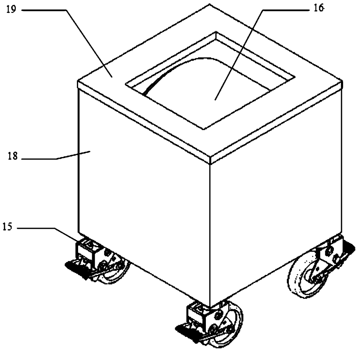
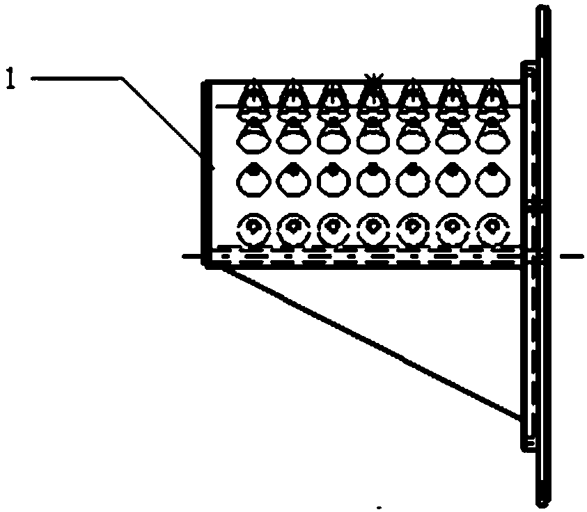
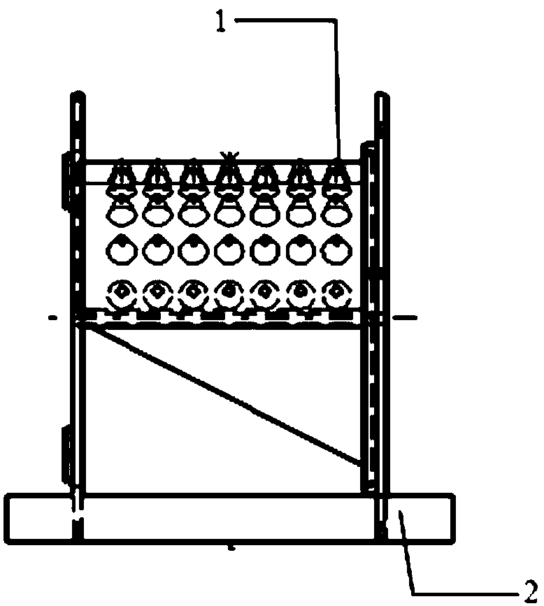
[0018] Such as Figure 1-8 As shown, a humidifying device includes a housing 18, a sponge support wheel 4, an air storage tank 1, an air pipe 9, and a control box 8; a glass water level visual tube 17 is hung on the outside of the housing 18, and a support wheel 15 is installed on the bottom. A cover plate 19 is provided with an opening. The air pipe 9 passes through the housing 18 and enters the interior of the housing 18. The cylinder body of the gas storage tank 1 is evenly distributed with inverted tapered air outlets. The sponge support wheel 4 is set on the gas storage tank 1. The surface is wound with a water-absorbing sponge body 16, and they are installed together in the inner shell support body 2. A limit adjustment ring 5 is provided at one end of the sponge support wheel 4, and an impeller 3 and a transmission key 14 are installed at the other end, and an air nozzle 10 is provided above the impeller 3. , tap water is injected from the opening of the cover plate 19,...


PUM


Abstract

The invention discloses a humidifying device. The humidifying device comprises a shell, a sponge supporting wheel, a gas storage cylinder, an air pipe and a control box; a glass water level visual tube is hung on the outer side of the shell, a cover plate with an opening is arranged at the top of the shell, the air pipe penetrates into the shell through the shell, tap water is injected from the opening of the cover plate, the dried compressed air enters the control box through the air pipe, the compressed air is divided into two parts, an air nozzle control valve is used for distributing partof air to an air nozzle, the air nozzle pushes an impeller to drive the sponge supporting wheel to rotate through a transmission key, the humidifying quantity control valve is used for adjusting the flow of the other part of air and then supplying air to the gas storage barrel through the air pipe, air in the air storage barrel penetrates through the air outlet and the sponge supporting wheel, humidified air is formed through the soaked sponge, the air after humidifying passes through the opening of the cover plate and overflows to humidify the environment.

Description

technical field [0001] The invention relates to the technical field of atomizers, in particular to a humidifying device. Background technique [0002] In the field of aircraft manufacturing, the glue coating and sealing work of fuel tanks needs to work in a relatively constant temperature and humidity environment. Generally, the construction of fuel tank sealants needs to be carried out under the conditions of ambient temperature 18°C-35°C and relative humidity 30%-90%. After the sealant is mixed and applied, its cure rate varies significantly with changes in temperature and relative humidity. Generally speaking, under the condition of low temperature and low humidity, the curing is very slow, otherwise, the curing is accelerated. At this time, appropriate heating and humidification measures are allowed to accelerate the curing. [0003] Especially in the northwest region, the temperature of the plant has been around 15°C and the humidity has been 15%-20% since winter. The ...

Claims


Application Information

Patent Timeline
Patent Type & Authority Applications(China)
IPC IPC(8): F24F6/06
CPCF24F6/06
Inventor 刘义明罗群仲小惠刘博锋
Owner XIAN AIRCRAFT IND GROUP
Learn More