Clamping mechanism for vibrating wire strain sensor calibration device

A strain sensor and calibration device technology, applied in the direction of mechanical solid deformation measurement, etc., can solve the problems of low calibration efficiency, device deformation, and high calibration labor intensity, and achieve the effect of improving measurement accuracy and reducing Abbe error.

Pending Publication Date: 2019-02-19
HENAN PROVINCE INST OF METROLOGY
View PDF2 Cites 3 Cited by
  • Summary
  • Abstract
  • Description
  • Claims
  • Application Information

AI Technical Summary

Problems solved by technology

In recent years, some domestic institutions have also designed calibration devices according to the specifications. For example, Chinese patent CN101738157A discloses a vibrating wire strain sensor calibration device, which is mainly of a purely mechanical structure and uses a dial indicator for measurement. Calibration is labor-intensive, calibration efficiency is low, and it is difficult to obtain repeatability errors
Chinese patent CN107621222A discloses a vibrating wire strain gauge calibration device. During the calibration process, the tiny length variation is measured, but the sliding problem in the clamping part of the sensor has a great influence on the calibration result; When the large-range vibrating wire sensor is calibrated, the device will be deformed, and the stiffness of the device cannot meet the calibration requirements
[0004] During the calibration process, the clamping stability of the vibrating wire strain sensor is relatively high. However, there is no special vibrating wire strain sensor clamping device for the calibration device of the vibrating wire strain sensor.

Method used


Image

  • Clamping mechanism for vibrating wire strain sensor calibration device
  • Clamping mechanism for vibrating wire strain sensor calibration device
  • Clamping mechanism for vibrating wire strain sensor calibration device

Examples


Embodiment Construction

[0016] The present invention will be further described below in conjunction with the accompanying drawings.

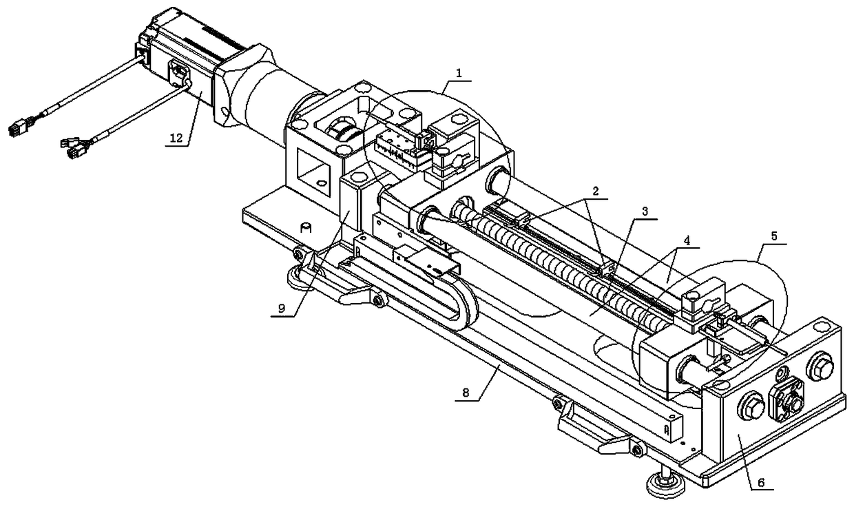
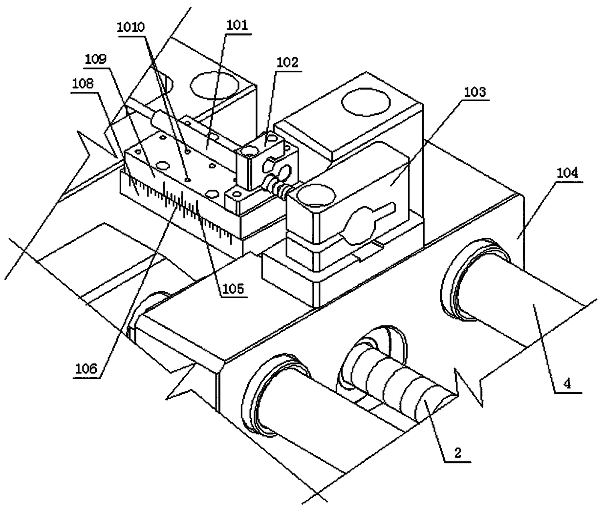
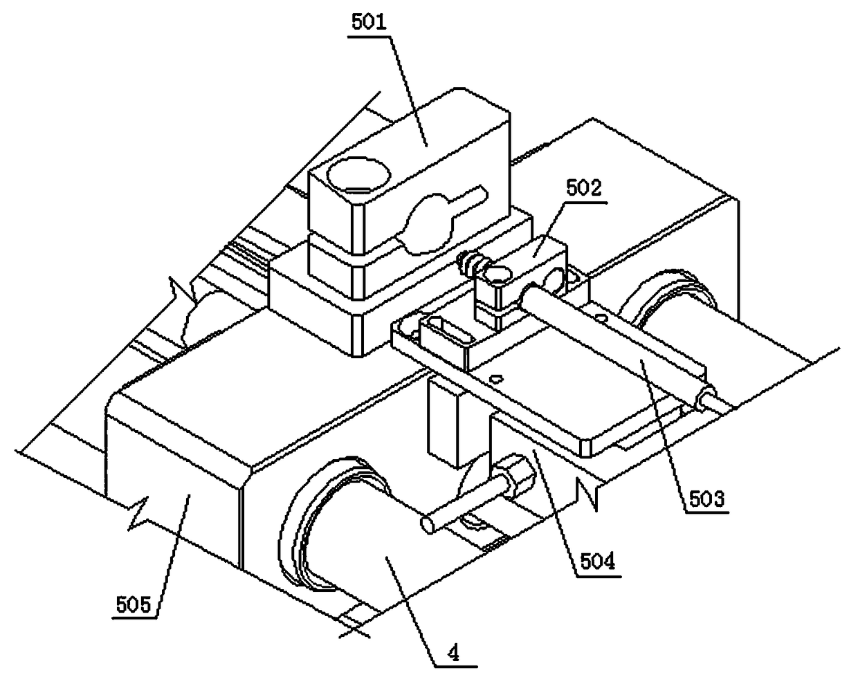
[0017] Such as Figure 1 to Figure 3 As shown, at first the present invention is assembled on the special vibrating wire strain sensor calibration device for use, wherein the vibrating wire strain sensor calibration device includes a base 8, a left fixed seat 9 is fixed at the left end of the base 8, and a The right end is fixed with a right fixed seat 6, between the left fixed seat 9 and the right fixed seat 6, a guide slide bar 4 is fixed, a power lead screw 3 is connected in rotation, and the clamping mechanism of the present invention is assembled on the left fixed seat 9 and the right fixed seat. Between the seats 6, specifically, the clamping mechanism of the present invention includes a left clamp 1 and a right clamp 5, the left clamp 1 includes a left slider 104, and the left slider 104 is sleeved on the guide slider 4 and the power wire The left half of the b...


PUM


Abstract

The invention discloses a clamping mechanism for a vibrating wire strain sensor calibration device, comprising left and right clamps. The left clamp comprises a left slider, which is provided with a left smooth punch hole for passing through the guide slide, and a left threaded punch hole for screwing the power screw. A left clamping head is fixed on the top of the left slider. The right clamp comprises a right slider, which is provides with a right smooth punch hole for passing through the guide slide, and a right smooth punch hole for passing through the power screw. A right clamping head isfixed at the top of the right slider. The left and right displacement sensors simultaneously detect the sliding amount of the left and right ends of the vibrating wire strain sensor, which improves the measurement accuracy and also detects the stress change in real time.

Description

technical field [0001] The invention belongs to the technical field of measurement and calibration equipment, and in particular relates to a clamping mechanism for a calibration device of a vibrating wire strain sensor. Background technique [0002] The vibrating wire strain sensor is a more advanced sensor in the current stress and strain measurement. This sensor outputs frequency instead of voltage, and will not cause obvious signal attenuation due to changes in wire resistance and temperature fluctuations. It has a simple structure and high precision. , strong anti-interference ability, long signal transmission distance, good long-term stability, etc., can be applied in harsh environments such as low temperature, high temperature, high radiation, etc., and have been widely used in dams, bridges, large buildings, subways, shipbuilding, mines, Safety early warning and safety inspection in coal mines, foundation pits, water conservancy and hydropower, petrochemical, nuclear ...

Claims


Application Information

Patent Timeline
Patent Type & Authority Applications(China)
IPC IPC(8): G01B5/30
CPCG01B5/30
Inventor 王一凡王晓伟贾晓杰邹晓华张红岩毛森牛国栋李博王伟鹏
Owner HENAN PROVINCE INST OF METROLOGY
Why Eureka
Try Eureka