Detection method of underground utility corridor based on wireless sensor network

A wireless sensor and underground pipe corridor technology, applied in the field of wireless communication, can solve problems such as prolonging the network life cycle, not considering node positions and remaining energy, and losing node energy, etc., achieving fast and convenient processing speed, accurate and reliable evaluation results, and increased The effect of precision

Active Publication Date: 2021-05-25
HANGZHOU DIANZI UNIV
View PDF9 Cites 0 Cited by
  • Summary
  • Abstract
  • Description
  • Claims
  • Application Information

AI Technical Summary

Problems solved by technology

This algorithm is relatively easy to implement, but it also has many shortcomings
First, when selecting a cluster head, it is determined by generating a random number and comparing it with the set threshold, but does not consider the position of the node and the remaining energy
Just imagine that if there are too few neighbor nodes around a node, if it is used as a cluster head, the reliability of the collected data will be lower
Second, the default transmission path is a single-hop route, which consumes more energy and increases the loss rate of transmission packets, which is not conducive to prolonging the life cycle of the network
Third, since a new cluster head needs to be re-selected in each round, it will take a lot of time on the one hand, and on the other hand, it will also consume a lot of node energy during the selection process

Method used


Image

  • Detection method of underground utility corridor based on wireless sensor network
  • Detection method of underground utility corridor based on wireless sensor network
  • Detection method of underground utility corridor based on wireless sensor network

Examples


Embodiment Construction

[0048] The present invention will be further described below.

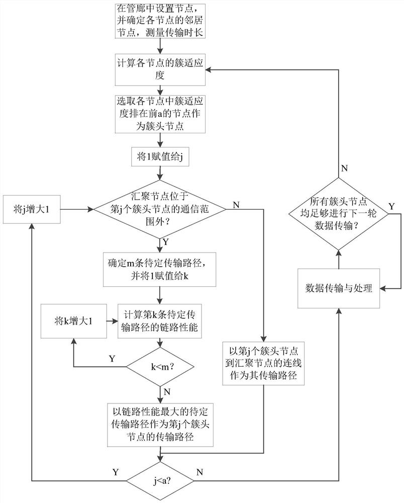
[0049] Such as figure 1 As shown, a wireless sensor network detection method for underground pipe gallery, the specific steps are as follows:

[0050] Step 1: Set up converging nodes and n common nodes in the underground pipe gallery. Common nodes are divided into gas sensors (hydrogen sulfide gas sensors are used in this embodiment), pressure sensors, temperature and humidity sensors and smoke sensors. The sink node is the base station for sending, receiving and processing data, and it is located in the center of the underground pipe gallery.

[0051] Traverse all surviving common nodes in the wireless sensor network. Determine the number of neighbor nodes for each common node. If an ordinary node is located within the transmission range of another ordinary node, the two nodes are their respective neighbor nodes. Measure the time required for each ordinary node to transmit data to all its corresponding neigh...


PUM


Abstract

The invention discloses an underground utility gallery detection method based on a wireless sensor network. The existing wireless sensor clustering algorithm does not consider the position of the nodes and the remaining energy, which consumes a lot of energy and has a high loss rate of transmission packets. The present invention is as follows: 1. Lay common nodes and convergence nodes, and determine the number of neighbor nodes of each node. 2. Calculate the cluster fitness, and perform clustering according to the cluster fitness, and determine the information transmission path of the non-cluster head nodes in each cluster. 3. Establish a coordinate system with the origin of the converging nodes. 4. Confirm the information transmission path from each cluster head node to the sink node. 5. Each common node performs data detection and transmits the obtained data to the sink node according to the information transmission path. 6. Judging re-clustering or re-detection according to the remaining energy of each cluster head node. The cluster head nodes selected by the present invention have sufficient energy and high data reliability. In the present invention, the cluster head node selects a path with better link performance to transmit data to the convergence node, so as to reduce the loss rate of transmission packets.

Description

technical field [0001] The invention belongs to the technical field of wireless communication, and in particular relates to a method and a system for detecting an underground utility gallery through a wireless sensor network. Background technique [0002] As a new type of network that can efficiently obtain environmental information, wireless sensor networks have huge applications in daily social activities, military affairs, and scientific research. In general, wireless sensor networks have a certain network hierarchy. First, select the node with more energy and good location as the cluster head; then, each other node joins the corresponding cluster, and selects the path that consumes the least energy to transmit information to the cluster head; finally, the cluster head selects the path that leads to the sink node with the least energy consumption. good path. In this way, the clustering work is completed. [0003] Among the clustering algorithms, the most commonly used ...

Claims


Application Information

Patent Timeline
Patent Type & Authority Patents(China)
IPC IPC(8): H04W4/38H04W40/10H04W40/20H04W40/22G06N3/04G01D21/02
CPCH04W4/38H04W40/10H04W40/20H04W40/22G01D21/02G06N3/045
Inventor 赵治栋许开达惠国华
Owner HANGZHOU DIANZI UNIV
Why Eureka
Try Eureka