Eureka AIR delivers breakthrough ideas for toughest innovation challenges, trusted by R&D personnel around the world.

Stable pipeline heat dissipation module

A heat dissipation module and stable technology, applied in the direction of indirect heat exchangers, lighting and heating equipment, etc., can solve the problem of low heat dissipation efficiency, achieve high heat dissipation efficiency, uniform distribution, and protect the effect of thermal interference

Pending Publication Date: 2019-02-22
SUZHOU YONGTENG ELECTRONICS PROD
View PDF0 Cites 1 Cited by
  • Summary
  • Abstract
  • Description
  • Claims
  • Application Information

AI Technical Summary

Problems solved by technology

However, at present, the heat pipe is usually directly in contact with the heating device for heat dissipation, and the heat dissipation efficiency is low.

Method used


Image

  • Stable pipeline heat dissipation module
  • Stable pipeline heat dissipation module
  • Stable pipeline heat dissipation module

Examples


Embodiment

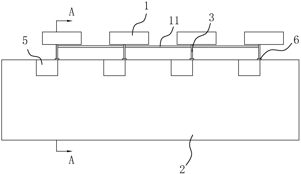
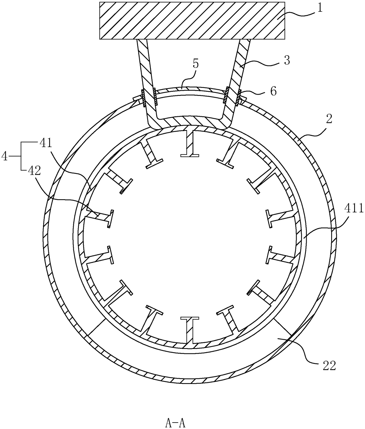
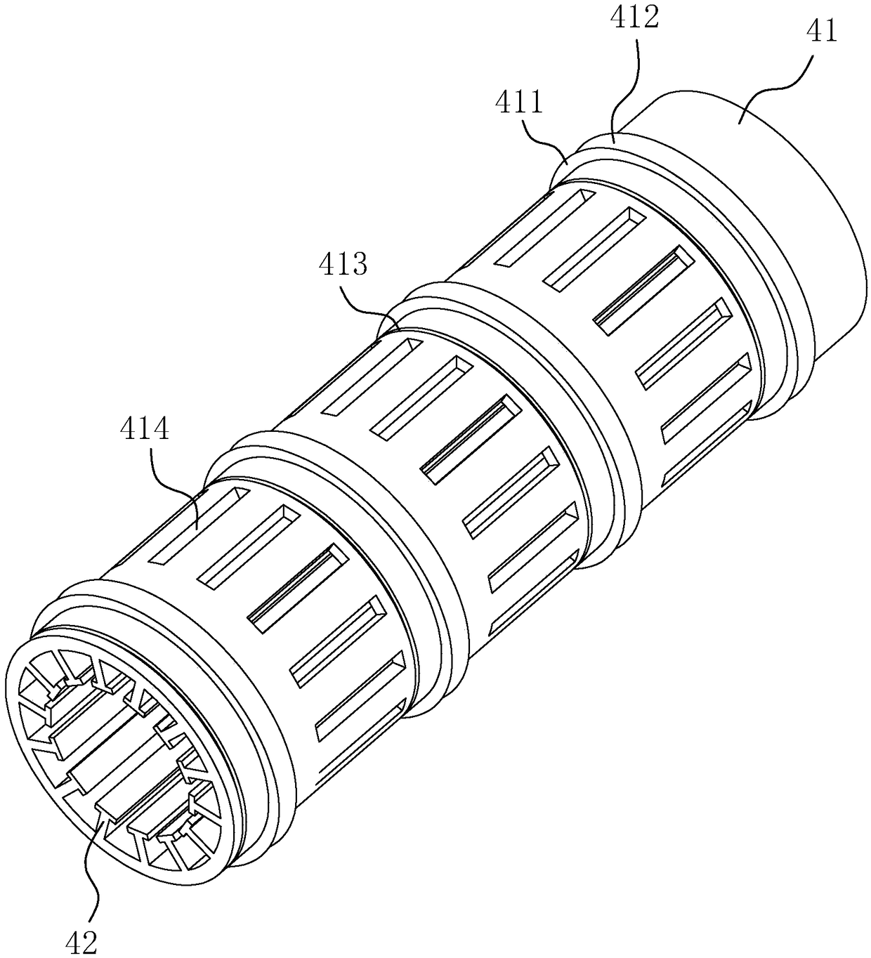
[0039] A stable pipe cooling module, such as figure 1 As shown, it includes: a number of heat absorbers 1 for assembling with the heating body, and a uniform heat pipe 11 is connected between adjacent heat absorbers 1; a diversion pipe 2, and a plurality of slots 21 are provided on the diversion pipe 2; The heat pipe 3 carried on the heat absorber 1; the heat dissipation structure 4 arranged in the flow guide pipe 2; and the sealing plate 5 carried on the flow guide pipe 2 for closing the slot 21, and the sealing plate 5 is provided with a heat conduction The socket 51 through which the tube 3 passes, and the sealing plate 5 is in sealing connection with the heat pipe 3 .

[0040] Specifically, the heat absorber 1 can be made of a material with good thermal conductivity such as copper alloy or aluminum alloy, which can be attached to the heating body so as to absorb and conduct the heat of the heating body. The uniform heat pipe 11 and the heat pipe 3 are evenly connected Con...


PUM


Abstract

The invention relates to a stable pipeline heat dissipation module. The stable pipeline heat dissipation module comprises a plurality of heat absorption bodies used for being assembled with a heatingbody, a flow guide pipeline provided with a plurality of insertion grooves, heat conducting pipes born on the heating bodies, a heat dissipation structure arranged in the flow guide pipeline, and a sealing plate born on the flow guide pipeline and used for sealing the insertion grooves, wherein the heat dissipation structure comprises a heat dissipation pipe and a plurality of heat dissipation blades arranged in the heat dissipation pipe; a contact ring is arranged on the outer wall of the heat dissipation pipe, and the heat conducting pipes inserted into the insertion grooves and bonded withthe contact ring; and insertion ports allowing the heat conducting pipes to penetrate through are formed in the sealing plate, and the sealing plate is in sealing connection with the heat conducting pipes. Higher heat dissipation efficiency is achieved due to large contact area of the heat dissipation pipe, the heat dissipation blades and a heat dissipation medium; and moreover, the influence of an external environment on the heating body can be reduced through the pipeline heat dissipation, so that the heat interference of other electronic components or mechanical components is effectively avoided.

Description

technical field [0001] The invention relates to the technical field of heat dissipation devices, in particular to a stable pipe heat dissipation module. Background technique [0002] The heat dissipation method refers to the main way the radiator dissipates heat. In thermodynamics, heat dissipation is heat transfer, and there are three main ways of heat transfer: heat conduction, heat convection and heat radiation. The transfer of energy by itself or when matter comes into contact with matter is known as heat conduction, and it is the most common form of heat transfer. For example, the way that the heat sink base is in direct contact with the heat source to take away heat is heat conduction. Heat convection refers to the heat transfer method in which flowing fluid (gas or liquid) takes heat away. In the heat dissipation system of the chassis, the "forced heat convection" heat dissipation method in which the cooling fan drives the gas flow is more common. Thermal radiation...

Claims


Application Information

Patent Timeline
Patent Type & Authority Applications(China)
IPC IPC(8): F28D15/02
CPCF28D15/02F28D2021/0029
Inventor 许晋维
Owner SUZHOU YONGTENG ELECTRONICS PROD
Why Eureka
Eureka Blog
Learn More