
Synchronous condenser site selection method based on long distance power transmission

A long-distance, camera-adjusting technology, applied in the direction of AC network voltage adjustment, reactive power adjustment/elimination/compensation, reactive power compensation, etc. The effect of failure probability, improving the strength of the grid, and enhancing the voltage support capacity of the system

Active Publication Date: 2019-02-22
HARBIN UNIV OF SCI & TECH
View PDF6 Cites 9 Cited by
  • Summary
  • Abstract
  • Description
  • Claims
  • Application Information

AI Technical Summary

Problems solved by technology

[0005] The present invention can provide a site selection method for a synchronous condenser, which can improve the performance of a synchronous condenser in a multi-receiving AC-DC power transmission system, reduce the failure probability of local DC commutation and the failure probability of continuous commutation in a multi-DC system, and solve the problem of The problem of storage and consumption of distributed new energy

Method used


Image

  • Synchronous condenser site selection method based on long distance power transmission
  • Synchronous condenser site selection method based on long distance power transmission
  • Synchronous condenser site selection method based on long distance power transmission

Examples


comparative approach 1

[0060] Compared with Scheme 1, only static reactive power equipment is used for reactive power compensation in the comprehensive long-distance multi-receiving terminal AC-DC power transmission system of this embodiment;

comparative approach 2

[0061] Comparison scheme 2: In the comprehensive long-distance multi-receiving terminal AC-DC power transmission system of this embodiment, only static reactive power equipment and STATCOM are used for reactive power compensation.

[0062] For scheme 1, since the AC system at the receiving end has no dynamic reactive power support during the fault process, the busbar voltage of the converter station drops significantly, causing the DC transmission power to oscillate and drop sharply, such as Figure 4 , 5 As shown, a commutation failure occurs at the same time, such as Figure 6 shown.

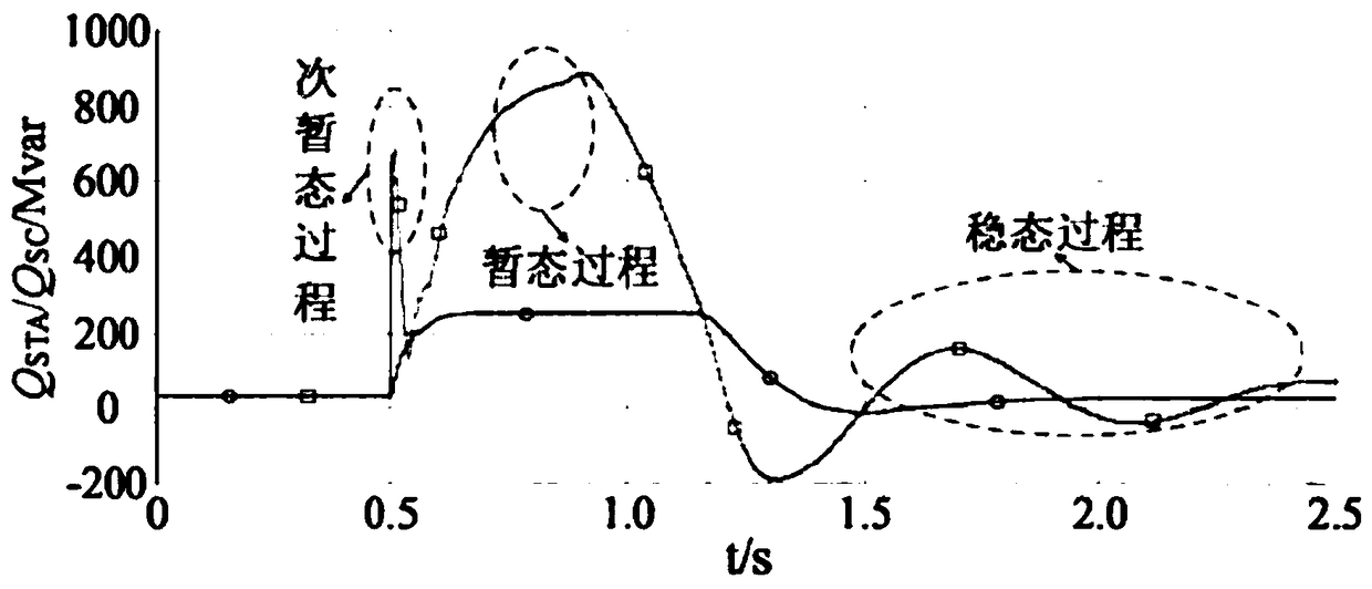
[0063] For scheme 2, during the fault process, STATCOM quickly adjusts its reactive power output, such as image 3 As shown, 220MVar dynamic reactive power support is provided to the AC system to improve the transient voltage stability of the AC system. Therefore, compared with Scheme 1, the busbar voltage drop, DC power transmission, and DC voltage shock and drop in the converter station h...


PUM


Abstract

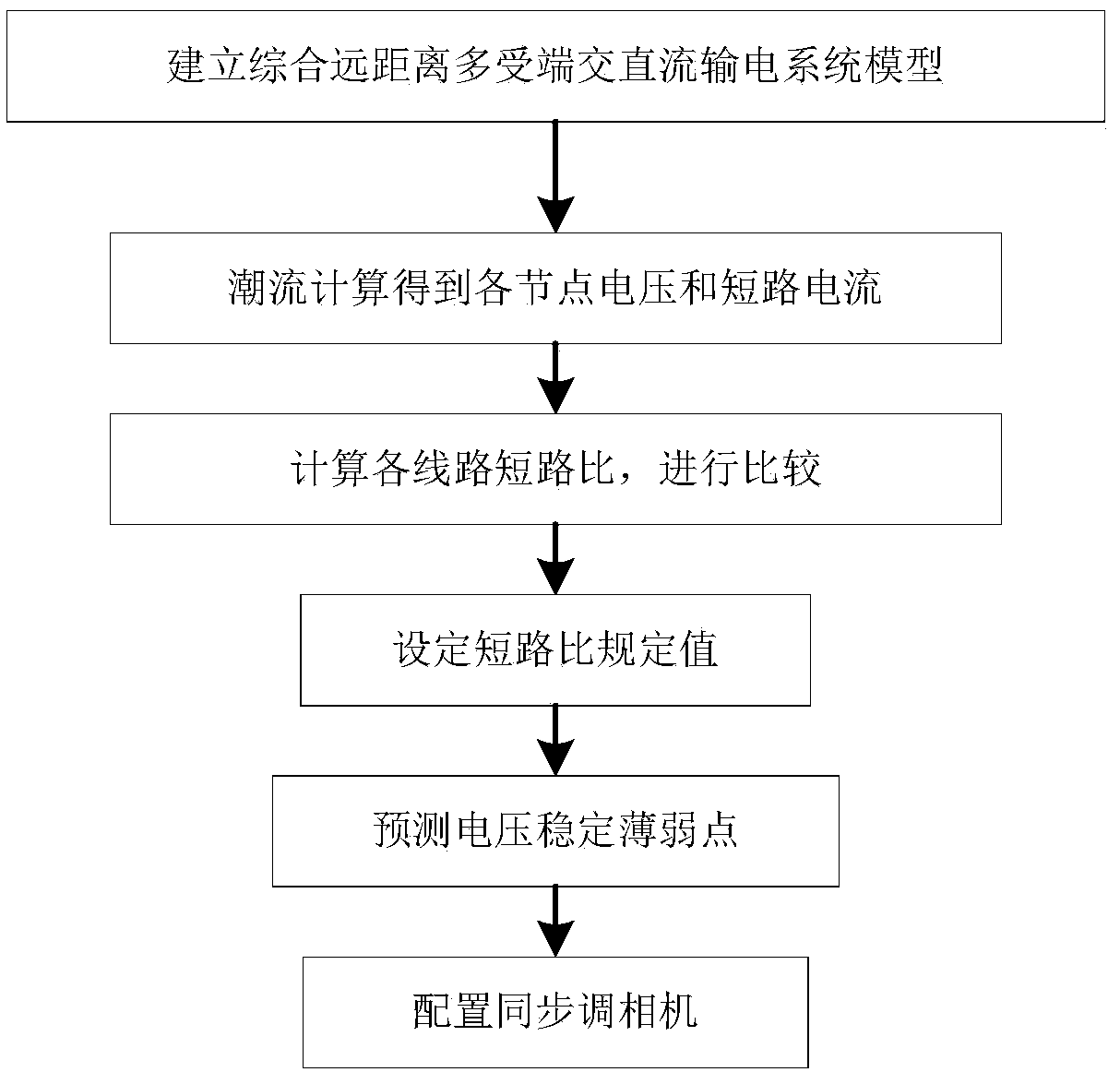
The invention discloses a synchronous condenser site selection method based on long distance power transmission, and belongs to the field of power transmission line reactive power compensation equipment site selection. The method solves the problem that local direct current commutation failure probability and multi-direct current system continuous commutation failure probability are high. The method establishes a power transmission system model according to actual power transmission situation. A power transmission system includes a power generation unit, a transmission unit and multiple receiving ends. The power generation unit includes conventional power stations and distributed new energy power stations. Three-phase short-circuit fault simulation analysis of the system is carried out byusing power system simulation software, and short-circuit current when a fault occurs is obtained through a system stability model. A short-circuit ratio of a direct current fed receiving alternatingcurrent system is calculated, a voltage stability weak point is predicted according to the short-circuit ratio of the direct current fed receiving alternating current system, and a synchronous condenser is arranged on a line where the weak point is located. The synchronous condenser site selection method based on the long distance power transmission cancels connection between all direct current systems and effectively improves grid strength of a multi-receiving end alternating current system, enhances the system voltage support capability and reduces the commutation failure probability.

Description

technical field [0001] This application relates to the field of site selection for reactive power compensation equipment for transmission lines. In particular, it relates to the site selection method of the synchronous condenser for long-distance power transmission in the multi-receiving terminal direct current transmission system. Background technique [0002] Synchronous condenser, also known as synchronous compensation machine. It is a reactive power compensation device, a synchronous motor that operates in the motor state and only provides or absorbs reactive power to the power system. The equipment in the power system needs to absorb a large amount of reactive power from the grid for its excitation. Therefore, a large part of the reactive current burdened by the grid will lead to a decrease in the power factor of the grid, an increase in line loss and voltage loss, and a deterioration in the quality of power transmission, which will seriously affect the stability of p...

Claims


Application Information

Patent Timeline
Patent Type & Authority Applications(China)
IPC IPC(8): H02J3/18H02J3/16
CPCH02J3/16H02J3/18Y02E40/30
Inventor 吕艳玲徐春婷侯仕强杜建烨付敏白红哲
Owner HARBIN UNIV OF SCI & TECH
Learn More