Oil-in-water emulsion electric field demulsification apparatus

A technology of oil-in-water emulsion and demulsification device, which is applied in the directions of grease/oily substance/float removal device, magnetic field/electric field water/sewage treatment, liquid separation, etc. Complex and other problems, to achieve the effect of simple main structure and easy installation

Inactive Publication Date: 2019-02-26
TIANJIN UNIV
View PDF4 Cites 2 Cited by
  • Summary
  • Abstract
  • Description
  • Claims
  • Application Information

AI Technical Summary

Problems solved by technology

These equipments occupy a large area, need to invest a lot of manpower, material resources and funds, have low efficiency, high energy consumption, poor adaptability, serious secondary pollution, consume a lot of chemicals, and the cost is too high
At the same time, membrane separation equipment and adsorption equipment are likely to cause pollution and clogging of membranes and adsorbents, the treatment process is complicated, and the process takes a long time

Method used


Image

  • Oil-in-water emulsion electric field demulsification apparatus
  • Oil-in-water emulsion electric field demulsification apparatus
  • Oil-in-water emulsion electric field demulsification apparatus

Examples


Embodiment 1

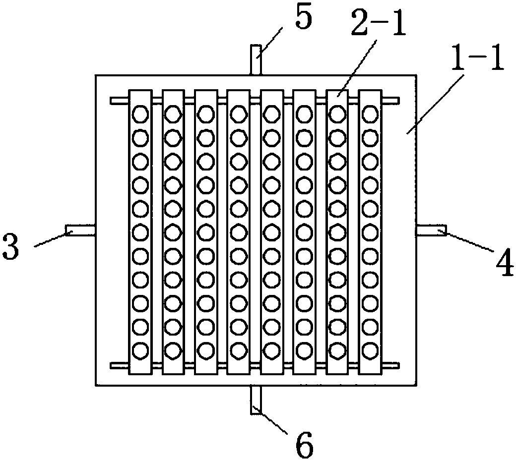
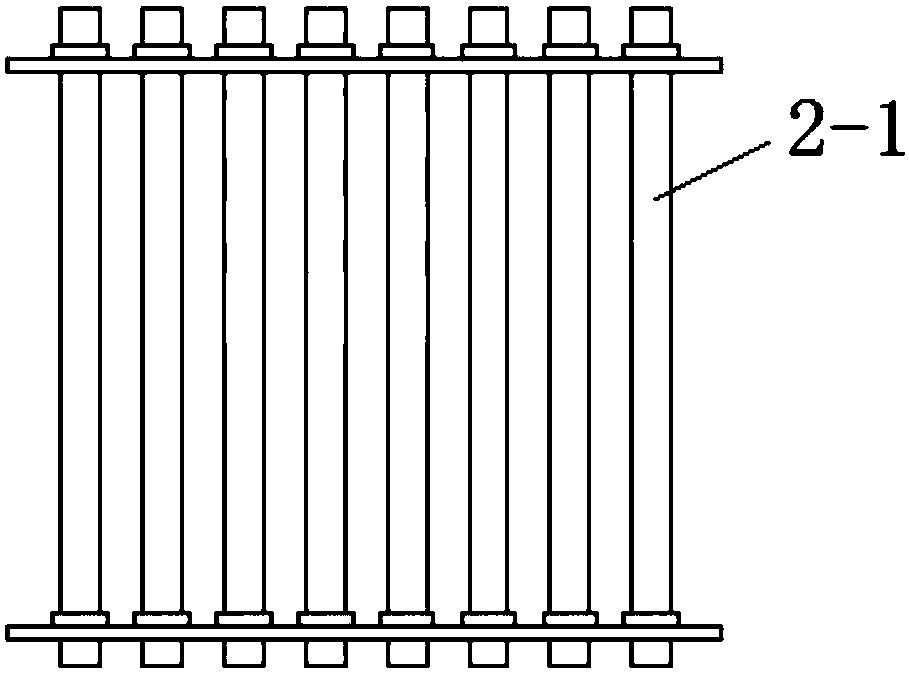
[0044] Static experiment: take 1000mL oil-in-water emulsion, the oil content is 0.5%. Under the conditions of voltage 800v, ​​frequency 50Hz, and duty cycle 50%, it acts for a total of two hours. The main body of the oil-water separator is a square cylinder, and the electrode assembly is an integrated rectangular electrode assembly. The number of single electrodes installed is 50, the distance between adjacent electrodes is 10mm, and the diameter of a single electrode is 5mm. The distance between the electrode assembly and the inner wall of the oil-water separator is kept at 15 mm, and the four rod-shaped metal electrodes located in the center of the orifice plate are used as positive electrodes, and the rest are used as negative electrodes. After the electric field is applied, the demulsification rate reaches 94.53%.

Embodiment 2

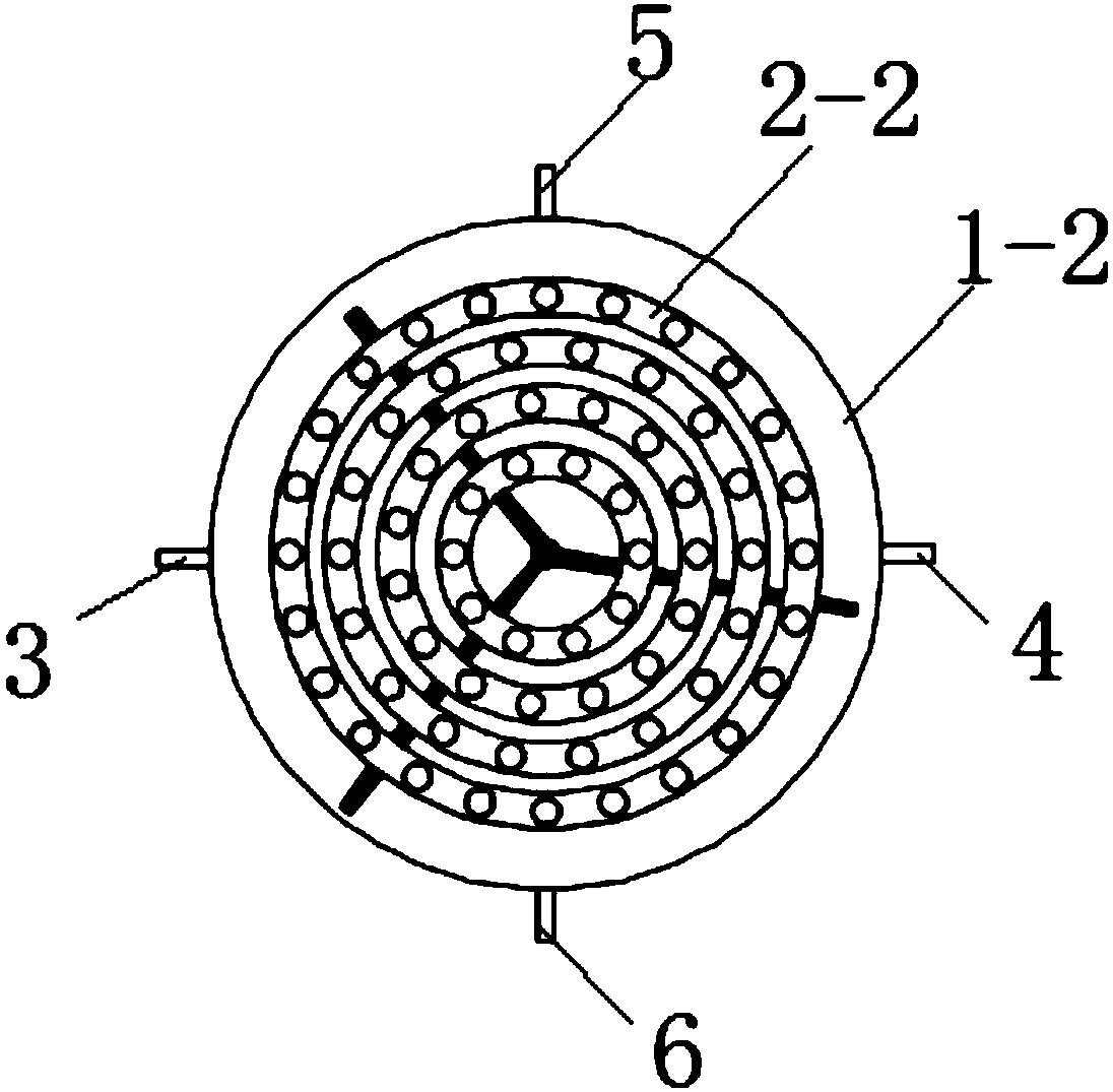
[0046] Static experiment: take 1000mL oil-in-water emulsion, the oil content is 0.5%. Under the conditions of voltage 900v, frequency 75Hz, and duty cycle 50%, it works for a total of two hours. The main body of the oil-water separator is a circular cylinder, and the electrode assembly is an integrated ring-shaped arrangement of electrode assemblies. The number of single electrodes installed is 47, the angle difference between adjacent electrodes is 30°, and the diameter of a single electrode is 5mm. The electrode assembly The distance from the inner wall of the oil-water separator is kept at 12mm, and one metal electrode located in the center of the orifice plate is used as the positive electrode, and the rest are used as the negative electrode. After the electric field acts, its demulsification rate reaches 95.97%.

Embodiment 3

[0048] Static experiment: take 1000mL oil-in-water emulsion, the oil content is 1%. Under the conditions of voltage 1000v, frequency 50Hz, and duty cycle 30%, it works for a total of two hours. The main body of the oil-water separator is a square cylinder, and the electrode assembly is a split rectangular electrode assembly. The number of small units installed is 8, and the number of single electrodes installed is 64. The distance between adjacent electrodes is 5mm. The diameter is 5mm. The distance between the electrode assembly and the inner wall of the oil-water separator is kept at 10mm. The metal electrodes of 1-10 small units located on the left side of the electrode assembly are used as positive electrodes, and the rest are used as negative electrodes. After the electric field is applied, the demulsification rate reaches 98.61%.


PUM

PropertyMeasurementUnit
lengthaaaaaaaaaa
widthaaaaaaaaaa
diameteraaaaaaaaaa

Abstract

The invention discloses an oil-in-water emulsion electric field demulsification apparatus, which comprises an oil-water separator and an electrode assembly, wherein the main body of the oil-water separator is a barrel-shaped structure with an opening on the upper end, the electrode assembly is arranged vertically inside the oil-water separator, and the outer wall of the oil-water separator is provided with an emulsion inlet, a water outlet, an oil outlet and an emulsion outlet. According to the present invention, the apparatus applies the alternating electric field in the oil-in-water emulsionby using the positive electrode and the negative electrode, such that the oil droplets aggregate and grow under the special electric field action on the oil droplets by the electric field so as to achieve the oil-water phase separation; and compared with other existing oil-in-water emulsion demulsification devices, the apparatus of the present invention has advantages of simple equipment, high demulsification efficiency, easy manufacture, low cost, environmentally-friendly demulsification process and wide application range, and can effective achieve the oil-water two-phase separation and recovery.

Description

technical field [0001] The invention belongs to the field of chemical separation equipment and relates to the technical direction of oil-water separation, in particular to an electric field demulsification device for oil-in-water emulsion. Background technique [0002] In recent years, with the deterioration of environmental pollution and excessive consumption of energy, the living environment of human beings has become more and more severe, and accidents caused by various pollutants have occurred frequently. At the same time, due to the excessive use of fossil resources such as oil, these non-renewable energy sources are already facing the fate of depletion. Therefore vigorously advocating and improving environmental quality and saving energy are very important issues that human beings are facing now. In terms of environmental pollutants, water pollution occupies an important position. Every year, industry and human life produce and discharge a large amount of sewage into...

Claims


Application Information

Patent Timeline
Patent Type & Authority Applications(China)
IPC IPC(8): C02F1/48C02F1/40
CPCC02F1/40C02F1/48
Inventor 康勇任博平张景源
Owner TIANJIN UNIV
Why Eureka
Try Eureka