Thin-wall shell processing method

A technology of thin-walled shells and processing technology, which is applied in metal processing equipment, metal processing machine parts, manufacturing tools, etc. It can solve problems such as inability to process, parts compacted and deformed, and affect the processing quality of parts, so as to achieve uniform pressing force Consistent, waste prevention, high degree of automation effect

Active Publication Date: 2019-03-01
河南红宇精密机械有限公司
View PDF6 Cites 12 Cited by
  • Summary
  • Abstract
  • Description
  • Claims
  • Application Information

AI Technical Summary

Problems solved by technology

[0003] The traditional process of processing thin-walled shell parts is completed by ordinary lathes and ordinary milling machines. During the processing, the use of general-purpose fixtures will cause uneven compression force, which will cause compression deformation to the parts, and manual processing by the operator will cause poor consistency and mass production. The time efficiency is low, and the processing quality is greatly affected by the technical level of the operator. Ordinary machine tools cannot process special shapes, such as elliptical holes, inclined-plane step holes, etc. In addition, multiple tool changes during the processing process, trial processing will affect the processing quality of parts , easily lead to waste

Method used


Image

  • Thin-wall shell processing method

Examples


Embodiment 1

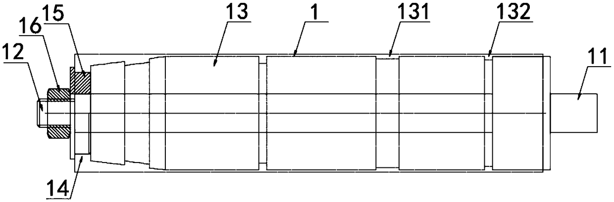
[0024] according to figure 1 A thin-walled shell processing method shown includes a tooling fixture 1, the tooling fixture 1 includes a mandrel 11, and one end of the mandrel 11 is provided with a mounting column 12, and the outer fixed sleeve of the mandrel 11 is provided with Outer ring body 13, a wide annular groove 131 and a thin annular groove 132 are provided on the outer ring body 13, a step 14 is provided between one end of the outer ring body 13 and the mandrel 11, and the outside of the step 14 is sleeved with Auxiliary pressure plate 15, the side of described auxiliary pressure plate 15 is provided with nut 16, and described nut 16 is threadedly connected with mounting column 12, and specific processing method is as follows:

[0025] Step 1: Rough turning of the outer wall, first rough turning the outer wall of the thin-walled shell, cutting off most of the machining allowance on the machined surface, and leaving an allowance of 3mm;

[0026] Step 2: Tempering at h...

Embodiment 2

[0034] according to figure 1 A thin-walled shell processing method shown includes a tooling fixture 1, the tooling fixture 1 includes a mandrel 11, and one end of the mandrel 11 is provided with a mounting column 12, and the outer fixed sleeve of the mandrel 11 is provided with Outer ring body 13, a wide annular groove 131 and a thin annular groove 132 are provided on the outer ring body 13, a step 14 is provided between one end of the outer ring body 13 and the mandrel 11, and the outside of the step 14 is sleeved with Auxiliary pressure plate 15, the side of described auxiliary pressure plate 15 is provided with nut 16, and described nut 16 is threadedly connected with mounting column 12, and specific processing method is as follows:

[0035] Step 1: Rough turning of the outer wall, first rough turning the outer wall of the thin-walled shell, cutting off most of the machining allowance on the machined surface, and leaving an allowance of 4mm;

[0036] Step 2: Tempering at h...

Embodiment 3

[0044] according to figure 1 A thin-walled shell processing method shown includes a tooling fixture 1, the tooling fixture 1 includes a mandrel 11, and one end of the mandrel 11 is provided with a mounting column 12, and the outer fixed sleeve of the mandrel 11 is provided with Outer ring body 13, a wide annular groove 131 and a thin annular groove 132 are provided on the outer ring body 13, a step 14 is provided between one end of the outer ring body 13 and the mandrel 11, and the outside of the step 14 is sleeved with Auxiliary pressure plate 15, the side of described auxiliary pressure plate 15 is provided with nut 16, and described nut 16 is threadedly connected with mounting column 12, and specific processing method is as follows:

[0045] Step 1: Rough turning of the outer wall, first rough turning the outer wall of the thin-walled shell, cutting off most of the machining allowance on the machined surface, and leaving an allowance of 5mm;

[0046] Step 2: Tempering at h...


PUM


Abstract

The invention discloses a thin-wall shell processing method which comprises a tool clamp, wherein the tool clamp comprises a mandrel; one end of the mandrel is equipped with a mounting column; the outer part of the mandrel is fixedly equipped with an outer ring body in a sleeving mode; a wide ring-shaped slot and a narrow ring-shaped slot are formed in the outer ring body; a step is arranged between one end of the outer ring-shaped body and the mandrel; an auxiliary pressure plate is arranged on the outer part of the step in the sleeving mode; one side of the auxiliary pressure plate is equipped with a nut; and the nut is in threaded connection with the mounting column. The thin-wall shell processing method comprises the following specific steps: step I, outer wall rough turning; step II,high-temperature tempering; step III, left end surface turning; step IV, right end surface turning; step V, clamp mounting; step VI, outer wall fine turning; and step VII, appearance processing. The thin-wall shell processing method performs processing through a high-efficiency machine tool, and a thermal-treatment tempering distressing process is added to release part processing inner stress; andthe necessity of designing a special clamp is combined, so that processing deformation is prevented, and part processing quality requirements are guaranteed.

Description

technical field [0001] The invention relates to the technical field of thin-walled shell processing, in particular to a thin-walled shell processing method. Background technique [0002] The traditional processing of thin-walled parts is completed by a single machine tool, which is updated to the advanced processing method of computer programming control, special fixture positioning, and multi-tool participation. [0003] The traditional process of processing thin-walled shell parts is completed by ordinary lathes and ordinary milling machines. During the processing, the use of general-purpose fixtures will cause uneven compression force, which will cause compression deformation to the parts, and manual processing by the operator will cause poor consistency and mass production. The time efficiency is low, and the processing quality is greatly affected by the technical level of the operator. Ordinary machine tools cannot process special shapes, such as elliptical holes, incli...

Claims


Application Information

Patent Timeline
Patent Type & Authority Applications(China)
IPC IPC(8): B23P15/00B23B1/00B23Q3/00
CPCB23B1/00B23P15/00B23Q3/00B23Q2703/10
Inventor 王建伟陈明杨长庆谭企姚虎龙魏英军牛东尚杨芳罗长银李琼
Owner 河南红宇精密机械有限公司
Why Eureka
Try Eureka