

Integrated external rotor electric wheel integrated structure and assembly method
A technology of rotor electric wheel and assembly method, which is applied in the direction of power device, motion deposition, control device, etc., and can solve the adverse effects of vehicle ride comfort and riding comfort, the increase of the mean square value of tire vibration acceleration, and the increase of unsprung mass and other problems, to achieve the effect of improving dynamic characteristics, improving ride comfort, and improving ride comfort
- Summary
- Abstract
- Description
- Claims
- Application Information
AI Technical Summary
Problems solved by technology
Method used
Image

Examples
Embodiment 1
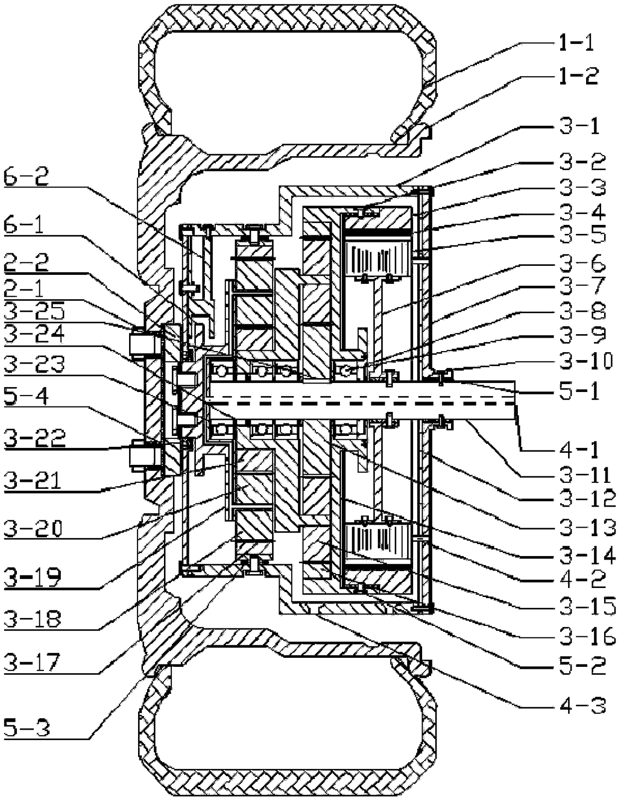
[0031] Figure 4 It is a structural principle diagram of Embodiment 1 of the present invention for vehicles. The structure and principle of embodiment 1 are as follows:
[0032] The stator and the coil winding 3-5 are fixed on the fixed shaft 3-11 through the stator support frame 3-6 and the vibration damping mechanism through the bolt connection, which ensures that the stator part remains stationary; the rotor 3-3 and the rotor ring gear 3-14 The vibration damping element 5-2 is bolted between them, and the rotor ring gear 3-14 acts as a support frame for the rotor 3-3, ensuring the normal operation of the rotor 3-3; the planetary reduction mechanism includes two stages, and the main structure includes the sun gear, Planetary gear, ring gear, and planet carrier, the first stage is fixed by the sun gear 3-13, the input of the ring gear 3-16, and the output of the planet carrier 3-18, when the motor is working, the rotor 3-3 rotates to drive the rotor ring gear 3-14 Rotate to...
Embodiment 2
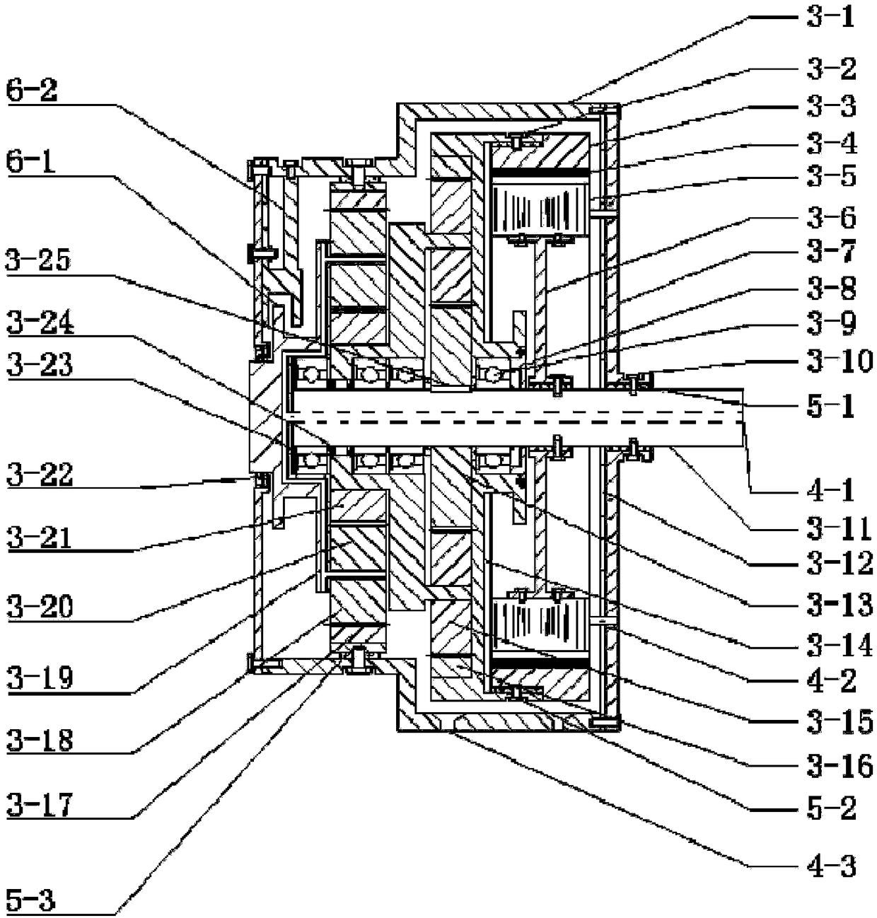
[0040] The concrete structure of embodiment 2 is as Figure 5 shown. The difference from Embodiment 1 is that the brake mechanism no longer brakes the planet carrier 3-19, but brakes the rotor ring gear 3-14, and other structures and components remain basically unchanged. The specific structure and working principle are as follows:
[0041] The brake disc of the brake is selected as the disc structure of the rotor ring gear 3-14, and the brake caliper 6-2 is connected to the stator support frame 3-6 through bolts and nuts. When the wheel needs to be braked, the brake caliper 6-2 The disk structure 5-1 of the rotor ring gear is braked, so that the rotor 3-3 stops rotating, and the vehicle stops moving forward. Compared with Embodiment 1, this design brakes the power source rotor 3-3, thereby greatly reducing the force required for braking, reducing the braking burden of the brake, and reducing the heat generated by the brake , to ensure the braking efficiency of the brake an...
PUM
 Abstract
Description
Claims
Application Information