Automatic cleaning device for residual yarn on the surface of spun bobbin

An automatic cleaning and spun yarn bobbin technology, applied in the textile field, can solve the problems of poor cleaning effect of residual yarn, high labor intensity of residual yarn cleaning, etc., and achieve the effect of improving cleaning effect, good residual yarn cleaning effect and high reliability.

Active Publication Date: 2020-07-21
HUBEI TIANMEN TEXTILE MACHINERY
View PDF8 Cites 0 Cited by
  • Summary
  • Abstract
  • Description
  • Claims
  • Application Information

AI Technical Summary

Problems solved by technology

[0003] The purpose of the present invention is to overcome the defects and problems existing in the prior art that the residual yarn cleaning labor intensity is high and the residual yarn cleaning effect is poor, and to provide a residual yarn cleaning device with low labor intensity and good residual yarn cleaning effect on the surface of the spun bobbin Automatic cleaning device

Method used


Image

  • Automatic cleaning device for residual yarn on the surface of spun bobbin
  • Automatic cleaning device for residual yarn on the surface of spun bobbin
  • Automatic cleaning device for residual yarn on the surface of spun bobbin

Examples


Embodiment 1

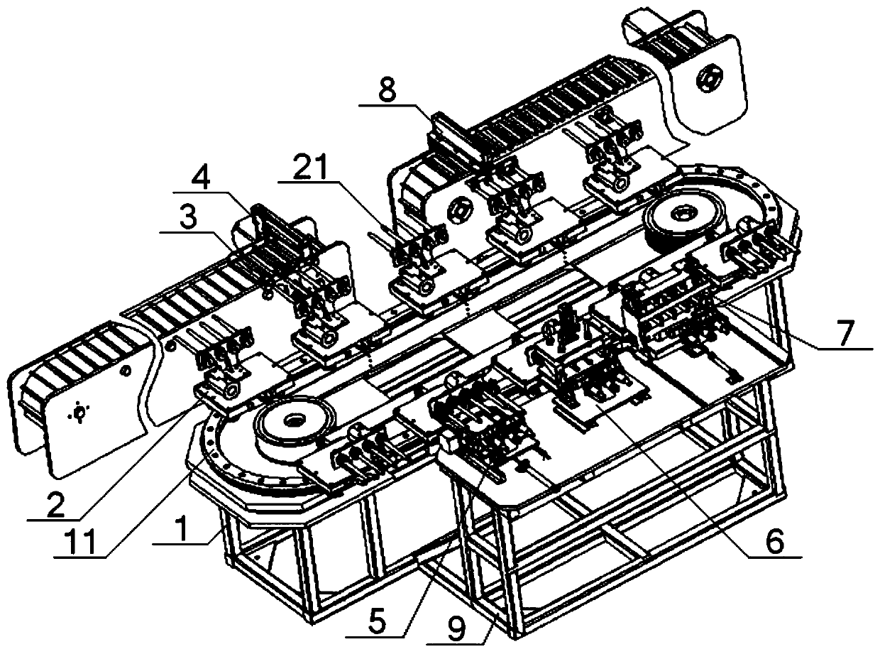
[0073] see figure 1 , Figure 12 , an automatic cleaning device for residual yarn on the surface of a spun bobbin, comprising a No. 1 frame 1 and an annular guide rail 11 arranged on it, a plurality of conveying carts 2 are slidably connected to the annular guide rail 11, and a plurality of sleeves are horizontally arranged on the conveying cart 2 Pipe 21, one side of the annular guide rail 11 is provided with a feeding mechanism 8 and a feeding mechanism 4 sequentially along the running direction of the conveying trolley 2, and the other side of the circular guide rail 11 is sequentially provided with a cutting mechanism along the running direction of the conveying trolley 2 5. Unwinding mechanism 6, yarn scraping mechanism 7;

[0074] The feeding mechanism 4 is used to load the spun bobbin 3 with residual yarn on the surface onto the casing 21;

[0075] The cutting mechanism 5 is used to cut the residual yarn on the surface of the spun bobbin 3;

[0076] The unwinding mec...

Embodiment 2

[0080] Basic content is the same as embodiment 1, the difference is:

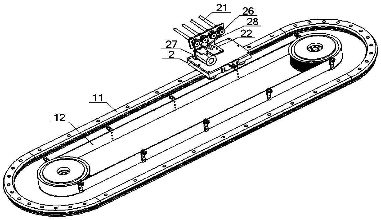
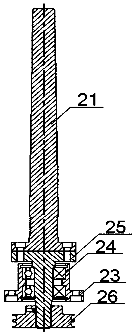
[0081] see figure 2 , image 3 , the conveying trolley 2 is provided with a connecting bracket 22, the connecting bracket 22 is provided with a plurality of bearing blocks 23, the bearing block 23 is equipped with a connecting rod 25 through a bearing 24, and one end of the connecting rod 25 is connected with the casing 21, The other end of the connecting rod 25 is sleeved with a No. 1 pulley 26, and the conveying trolley 2 is provided with a No. 1 rotating motor 27, and the output end of the No. 1 rotating motor 27 is connected with the No. 1 pulley 26 through a No. 1 belt 28.

Embodiment 3

[0083] Basic content is the same as embodiment 1, the difference is:

[0084] see figure 1 , Figure 4 , Figure 5 , the cutting mechanism 5 includes a No. 2 frame 9 and two No. 1 guide rails 51 arranged in parallel on it, a cutting platform 52 is slidably connected between the No. 1 guide rails 51, and the cutting platform 52 is connected with the No. 1 cylinder 53 , two No. 2 guide rails 54 are arranged in parallel on the cutting platform 52, and a moving base plate 55 is slidably connected between the two No. 2 guide rails 54, and the moving base plate 55 is connected with the No. Parallel No. 1 installation bracket 57 and No. 2 installation bracket 58, transmission shaft 59 is arranged between described No. 1 installation bracket 57 and No. 2 installation bracket 58, and the end of transmission shaft 59 is set with No. 2 belt pulley 510, No. 2 Belt pulley 510 is connected with No. 2 rotary motor 512 through No. 2 belt 511, and a plurality of cutting knives 513 are set o...


PUM


Abstract

The invention discloses an automatic cleaning device for residual yarn on the surfaces of fine yarn pipes. The automatic cleaning device comprises a first machine frame and an annular guide rail arranged on the first machine frame, wherein a plurality of conveying trolleys are slidably connected to the annular guide rail, and a plurality of sleeves are horizontally arranged on the conveying trolleys; a discharging mechanism and a feeding mechanism are arranged on one side of the annular guide rail in sequence in the running direction of the conveying trolleys, and a cutting mechanism, a backing-off mechanism and a yarn scraping mechanism are arranged on the other side of the annular guiding rail in sequence in the running direction of the conveying trolleys; the feeding mechanism is used for installing the fine yarn pipes with residual yarn on the surfaces on the sleeves; the cutting mechanism is used for cutting the residual yarn on the surfaces of the fine yarn pipes; and the backing-off mechanism is used for backing-off the residual yarn on the surfaces of the fine yarn pipes; the yarn scraping mechanism is used for scraping the residual yarn on the surfaces of the fine yarn pipes; and the discharging mechanism is used for removing the cleaned fine yarn pipes from the sleeves. The automatic cleaning device not only reduces the labor intensity of cleaning of the residual yarn, but also improves the effect of cleaning of the residual yarn.

Description

technical field [0001] The invention relates to the technical field of textiles, in particular to an automatic cleaning device for residual yarn on the surface of a spun bobbin, which is mainly suitable for reducing the labor intensity of cleaning residual yarn and improving the cleaning effect of residual yarn. Background technique [0002] The yarn is wound on the surface of the bobbin for the weaving and production process of spinning. Generally, when there is a small amount of yarn residue on the surface of the bobbin, the worker will replace the bobbin. In order to ensure the repeated use of the spun bobbin, it is necessary to manually remove the remaining yarn on the surface. Due to the huge amount of spun bobbin used in the spinning and production process, the labor intensity for workers to remove the residual yarn on the surface of the spun bobbin is high, and it takes time to remove the residual yarn. Cutting with blades is mostly used, which easily scratches the s...

Claims


Application Information

Patent Timeline
Patent Type & Authority Patents(China)
IPC IPC(8): B65H49/00B65G35/00B65G47/74
CPCB65G35/00B65G47/74B65G2201/0214B65H49/00
Inventor 左小艳张成俊张弛吴晓周向阳朱里
Owner HUBEI TIANMEN TEXTILE MACHINERY
Why Eureka
Try Eureka