Suction type emission reduction carrying device for gasoline engine

A gasoline engine and oil injection port technology, applied to engine components, machines/engines, charging systems, etc., can solve the problems of unsatisfactory emission reduction effects, large volume, complex structure, etc., and achieve easy installation and maintenance, and small volume , the effect of simple structure

Pending Publication Date: 2019-03-01
周伟传
View PDF6 Cites 2 Cited by
  • Summary
  • Abstract
  • Description
  • Claims
  • Application Information

AI Technical Summary

Problems solved by technology

[0003] As we all know, excessive exhaust emissions are currently the main cause of urban smog. With the current engine manufacturing technology, it is difficult to further improve the combustion efficiency from the engine structure, so how to reduce exhaust emissions has become an important issue of current public concern. Add ethanol gasoline to gasoline to reduce exhaust emissions or use a combustion accelerant to assist gasoline engine combustion to more fully reduce the content of harmful substances in exhaust gas, but the emission reduction effect of adding ethanol gasoline is not ideal, and can achieve a maximum emission reduction effect of about 30%; Accelerator assistance requires the addition of accelerant-carrying equipment, which may require changing the electrical circuit or structural distribution of the engine, and to achieve long-term and stable provision of accelerant equipment generally requires a larger volume and complex structure

Method used


Image

  • Suction type emission reduction carrying device for gasoline engine
  • Suction type emission reduction carrying device for gasoline engine
  • Suction type emission reduction carrying device for gasoline engine

Examples


Embodiment 1

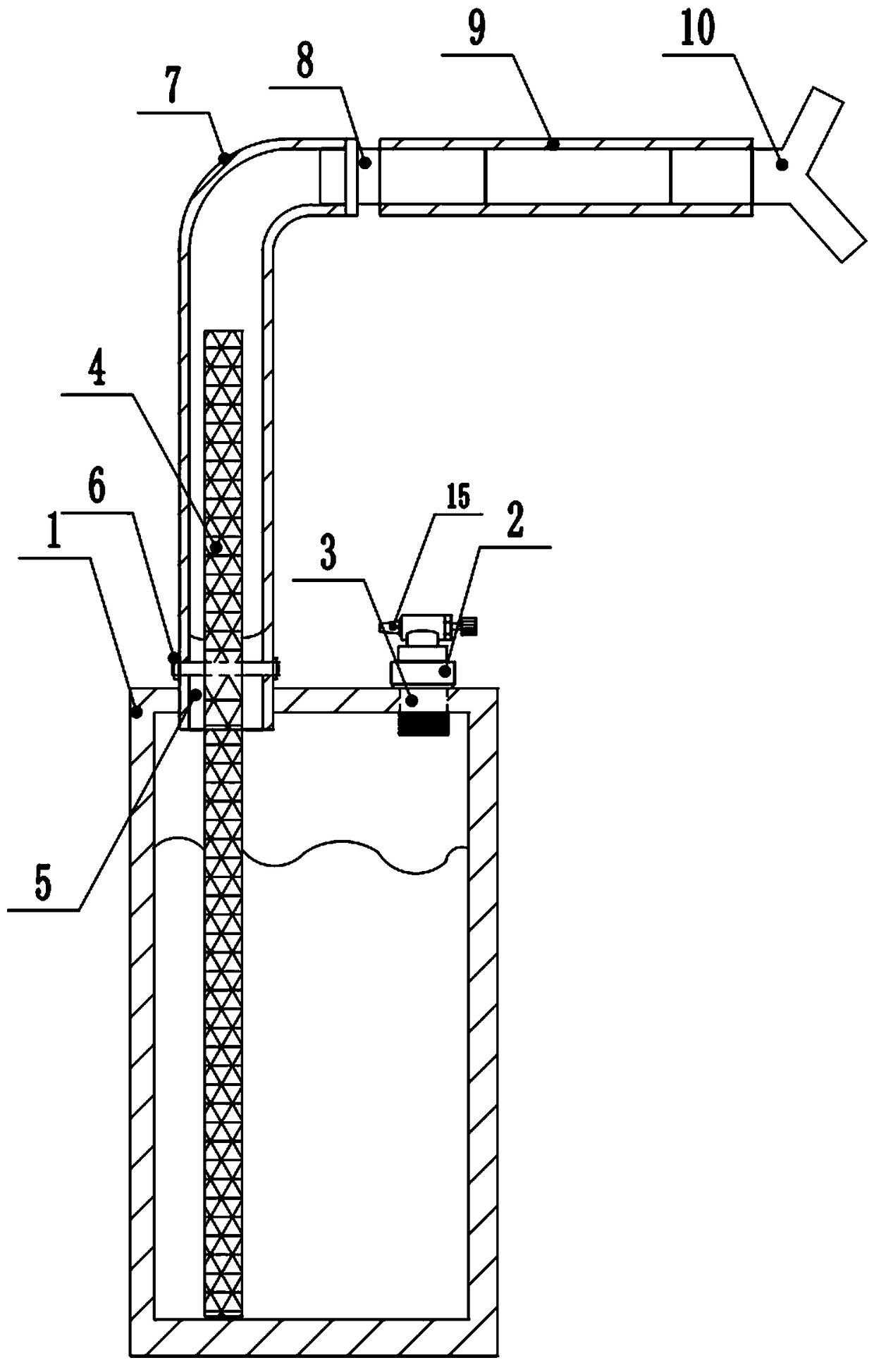
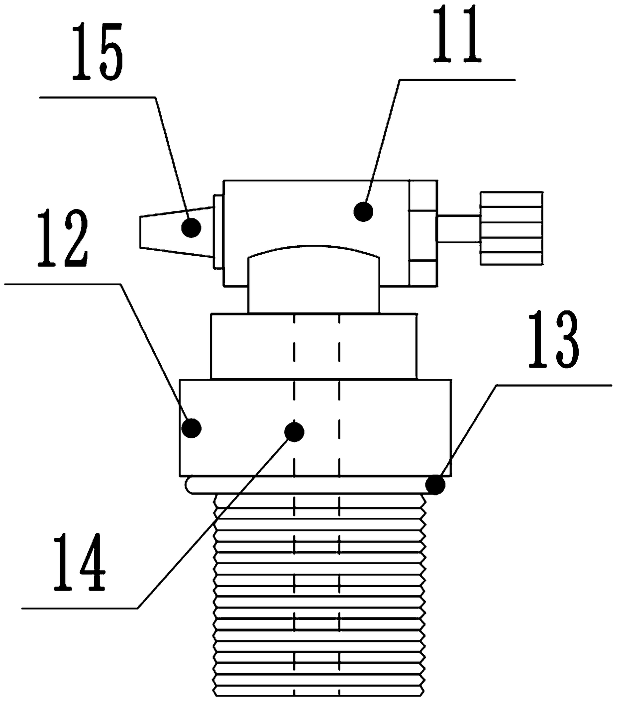
[0032] A suction type emission reduction carrying device for a gasoline engine, comprising: an oil storage tank 1, an oil filling bolt 2, an oil filling port 3, a wick 4, an oil outlet 5, a fixed bolt 6, an observation tube 7, and a conversion joint 8 , an oil outlet pipe 9 and a three-way valve 10, the top of the oil storage tank 1 is provided with an oil injection port 3 and an oil outlet 5, the inner wall of the oil injection port 3 has threads, the oil injection bolt 2 is threadedly connected with the oil injection port 3, and the wick cord 4 Insert the oil storage tank 1 from the oil outlet 5 to the bottom, insert the other end of the wick cord 4 into the observation tube 7, the observation tube 7 is fixedly connected with the oil outlet 5, and the other end of the observation tube 7 is connected to the oil outlet pipe through the conversion joint 8 9, and the other end of the oil outlet pipe 9 is connected with the three-way valve 10.

[0033] The oil filling bolt 2 is c...

Embodiment 2

[0037] A suction type emission reduction carrying device for a gasoline engine, comprising: an oil storage tank 1, an oil filling bolt 2, an oil filling port 3, a wick 4, an oil outlet 5, a fixed bolt 6, an observation tube 7, and a conversion joint 8 , an oil outlet pipe 9 and a three-way valve 10, the top of the oil storage tank 1 is provided with an oil injection port 3 and an oil outlet 5, the inner wall of the oil injection port 3 has threads, the oil injection bolt 2 is threadedly connected with the oil injection port 3, and the wick cord 4 Insert the oil storage tank 1 from the oil outlet 5 to the bottom, insert the other end of the wick cord 4 into the observation tube 7, the observation tube 7 is fixedly connected with the oil outlet 5, and the other end of the observation tube 7 is connected to the oil outlet pipe through the conversion joint 8 9, and the other end of the oil outlet pipe 9 is connected with the three-way valve 10.

[0038] The oil filling bolt 2 is c...


PUM


Abstract

Provided is a suction type emission reduction carrying device for a gasoline engine. The suction type emission reduction carrying device for the gasoline engine comprises an oil storage tank, an oil injecting bolt, an oil injection port, a wick rope, an oil outlet, a fixing bolt, an observing tube, a converting joint, an oil outlet pipe, and a three-way valve. The emission reduction carrying device is arranged in an automobile engine chamber, and connects an electromagnetic valve outlet end of a carbon tank and an inlet manifold through the three-way valve. The siphon effect of the wick rope in the observing tube is utilized to fit with an inlet regulating valve on the oil injecting bolt to stably and effectively suck combustion improvers stored in the oil storage tank into the inlet manifold of the engine to mix with air, thereby improving the combustion efficiency of the engine fuel.

Description

technical field [0001] The invention relates to the field of auto parts, in particular to a suction type emission reduction carrying device for a gasoline engine. Background technique [0002] At present, the core gasoline engine of mainstream automobiles on the market usually has a thermal efficiency of only about 30%, and a combustion efficiency of about 35%, which means that the fuel injection through the fuel injector and the air introduced by the intake manifold form an oil mixture in the cylinder bore. After the gas is ignited, there is still most of the invalid heat energy dissipated, and the incompletely burned fuel produces carbon monoxide and other waste gases and harmful substances are discharged from the exhaust pipe into the atmosphere. [0003] As we all know, excessive exhaust emissions are currently the main cause of urban smog. With the current engine manufacturing technology, it is difficult to further improve the combustion efficiency from the engine struc...

Claims


Application Information

Patent Timeline
Patent Type & Authority Applications(China)
IPC IPC(8): F02M37/00F02M37/02F02M37/50
CPCF02M37/0011F02M37/0017F02M37/0076F02M37/0082F02M37/02
Inventor 周伟传周钰淇
Owner 周伟传
Why Eureka
Try Eureka