

Inner flame tube applicable to radiant tube and radiant tube
A technology of radiant tubes and inner tubes, applied in the field of radiant tubes, which can solve the problems of local heating, easy generation of internal stress, and large overall length of radiant tubes, and achieve the effect of improving temperature uniformity
- Summary
- Abstract
- Description
- Claims
- Application Information
AI Technical Summary
Problems solved by technology
Method used
Image

Examples
Embodiment 1
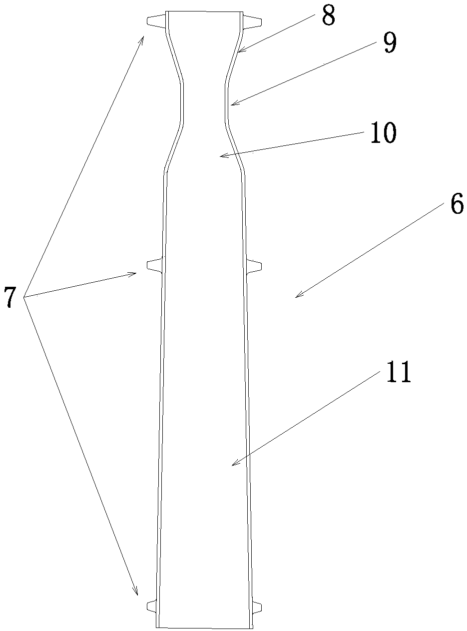
[0030] see figure 1 As shown, this embodiment is about a flame inner tube applied to a radiant tube, including an inner tube body 6, and the outer surface of the inner tube body 6 is uniformly distributed with supporting pieces 7 along the radial and axial directions. When the inner tube body 6 is placed on When inside the radiant tube body 5, it plays the role of limiting and fixing, and the form of its support sheet 7 includes but is not limited to radially as a group, distributing one or more support sheets 7, and axially distributing multiple groups of support sheets 7 at the same time, in order to ensure The inner tube body is not subject to thermal stress and other deformations, and two sets of supporting plates 7 are distributed in a staggered manner along the axial direction. °-135°-225°-315°.
[0031] The inner pipe body 6 is provided with a shrinkage pipe section 8, a straight pipe section 9 and an expansion pipe section 10 in sequence along the direction in which i...
Embodiment 2
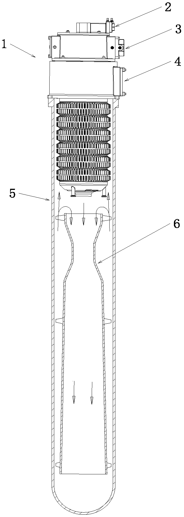
[0035] see figure 2 As shown, this embodiment provides a radiant tube with a built-in flame inner tube, including a radiant tube body 5 and an inner tube body 6,
[0036] The inner tube body 6 adopts the scheme as in Embodiment 1, and the radiant tube body 5 is a closed type radiant tube body 5 with a single-ended inlet. In the radiation tube body 5, the shrinkage tube section 8 is close to the inlet end of the radiation tube body 5, and the expansion tube section 10 is far away from the inlet end of the radiation tube body 5. There is a flue gas channel between the inner wall of the body 5 and the outer edge of the inlet and outlet ends of the flame inner tube 6, so that the flue gas enters the inner tube body 6 from the radiant tube body 5, reaches the end of the radiant tube body 5, and then flows backwards , flowing out through the flue gas channel.
[0037] In this embodiment, the outer structure of the radiant tube body 5 is an I-type radiant tube body with continuous...
Embodiment 3
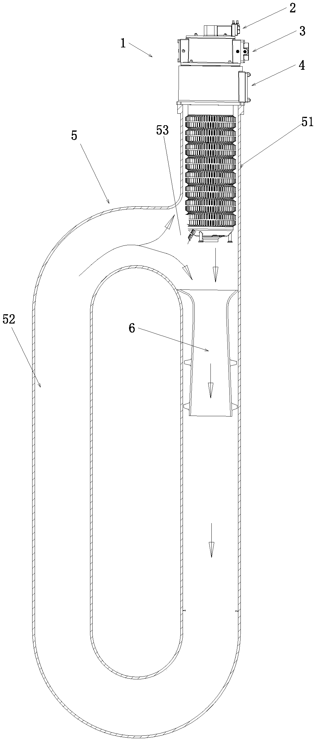
[0043] see image 3 As shown, the difference between the present embodiment and the second embodiment is that the radiation pipe body 5 in this embodiment is a closed type radiation pipe body 5 with a single-end inlet, and the radiation pipe body 5 flows in one direction in the same pipe section. The inner tube body 6 is arranged in the radiation tube body 5, wherein the shrink tube section 8 is close to the inlet end of the radiation tube body 5, and the expansion tube section 10 is far away from the inlet end of the radiation tube body 5. In the tube body 5, the outer diameter of the inlet end of the inner tube body 6 is not smaller than the inner diameter of the radiant tube body 5, so that the smoke flows out along the extending direction of the radiant tube body 5 after entering the inner tube body from the radiant tube body 5.
[0044] In this embodiment, the external structure of the radiant tube body 5 is a continuously extending P-type radiant tube body with the same ...
PUM
 Abstract
Description
Claims
Application Information