Real-time fluorescence detecting device of microreactor and operating method thereof

A technology of microreactor and real-time fluorescence, applied in fluorescence/phosphorescence, instruments, measuring devices, etc., can solve the problems of inability to detect multi-target molecules and detection system cannot achieve more channels, achieving high sensitivity and easy operation , the effect of improving accuracy

Pending Publication Date: 2019-03-01
SUZHOU HOTTOP INN INSTR TECH CO LTD CHINA +1
View PDF8 Cites 3 Cited by
  • Summary
  • Abstract
  • Description
  • Claims
  • Application Information

AI Technical Summary

Problems solved by technology

[0006] In view of the above-mentioned technical defects, the present invention proposes a real-time fluorescence detection device for a microreactor and its operation method, which solves the problem that the existing microreactor detection system cannot achieve more channels and cannot detect multi-target molecules

Method used


Image

  • Real-time fluorescence detecting device of microreactor and operating method thereof
  • Real-time fluorescence detecting device of microreactor and operating method thereof
  • Real-time fluorescence detecting device of microreactor and operating method thereof

Examples


Embodiment 1

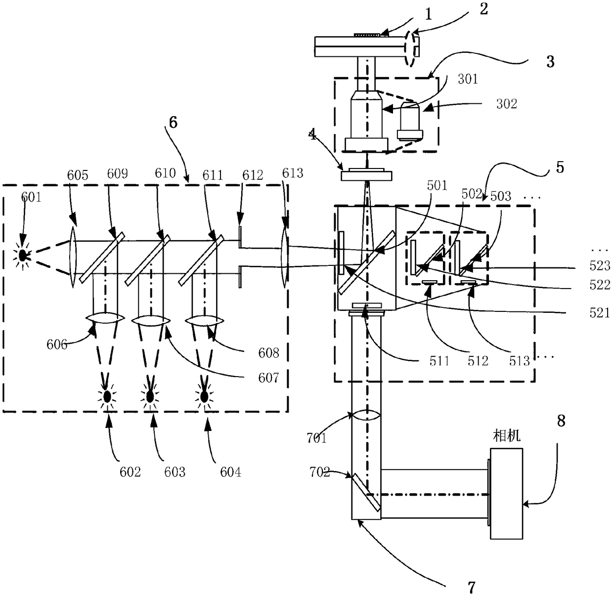
[0063] Such as figure 2 As shown, 601, 602, 603, 604 represent different lasers, 609, 610, 611, and 613 represent different first beam combiners, 612 represents the field diaphragm, and 605, 606, 607, and 608 represent different collimators. Lens, 301 and 302 represent different objective lenses. 501, 502, and 503 indicate different dichroic mirrors, 511, 512, and 513 indicate different filters in the imaging light path, and 521, 522, and 523 indicate different filters in the illumination light path.

[0064] The excitation light source of the light path diagram of the four-color fluorescence system is composed of four groups, each group of excitation light sources includes a laser and a collimating lens, and the laser and the collimating lens are matched. The light source chooses 405nm, 532nm, 638nm and 802nm wavelength fiber laser light source. 601 is an 802nm fiber laser, 602 is a 638nm fiber laser, 603 is a 532nm fiber laser, and 604 is a 405nm fiber laser.

[0065] Accordin...

Embodiment 2

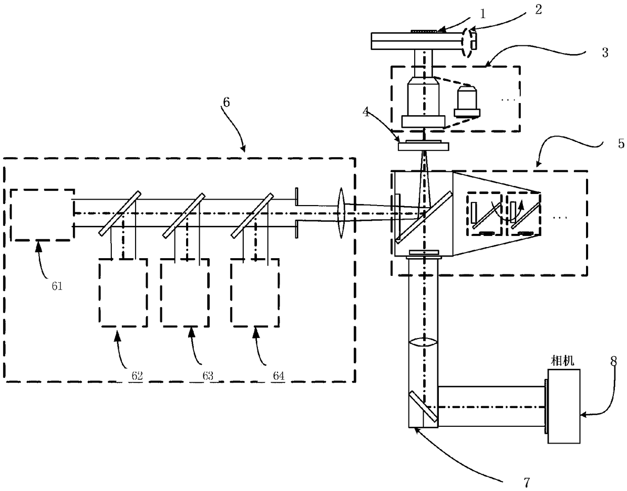
[0081] image 3 61 is the red band, 62 is the yellow band, 63 is the green-blue band, and 64 is the purple band. Figure 4 6101, 6102, 6103, 6104, 6201, 6202, 6203, 6204, 6301, 6302, 6303, 6304, 6401, 6402, 6403, 6404 indicate different lasers, 6105, 6106, 6107, 6108, 6205, 6206, 6207 , 6208, 6305, 6306, 6307, 6308, 6405, 6406, 6407, 6408 indicate different collimating lenses, 6109, 6110, 6111, 6209, 6210, 6211, 6309, 6310, 6311, 6409, 6410, 6411 indicate different The second beam combiner.

[0082] Such as image 3 with Figure 4 As shown, there are four groups of excitation light sources in the light path diagram of the sixteen-color fluorescence system, each group of excitation light sources includes four groups of second excitation light sources, and each group of second excitation light sources includes a laser, a collimator lens, and several second beam combiners. The lasers are matched with the collimating lens, and the second beam combiner is used to combine the beams of ...


PUM


Abstract

The invention discloses a real-time fluorescence detecting device of a microreactor and an operating method thereof. The real-time fluorescence detecting device of the microreactor comprises a biochip, a displacement platform, an objective lens component, an objective lens focusing device, an optical filter component, a light source device, an imaging light path component, a detector and a computer. The microreactor is placed in the biochip. The optical filter component is installed below the objective lens focusing device. The detector is connected with the optical filter component through the imaging light path component. The computer is electrically connected with the displacement platform, the objective lens focusing device and the detector. The light source device comprises exciting light sources, a field diaphragm and a first beam combining lens. There are multiple exciting light sources. The first beam combining lens is used for combining a light source of each exciting light source and forming a unified light path. The field diaphragm is installed in the unified light path after beam combining. The provided real-time fluorescence detecting device of the microreactor is capable of realizing multi-channel, high-sensitivity, large-area and rapid real-time detection to the microreactor.

Description

Technical field [0001] The invention relates to a detection electronic device, in particular to a real-time fluorescence detection device of a microreactor and an operation method thereof. Background technique [0002] A microreactor is a continuous flow pipeline type microreactor with a feature size between 1 and 300 microns manufactured by precision processing technology. A microreactor can contain millions of micro Channel, so it has a great specific surface area, heat exchange efficiency and mixing efficiency. Each microreactor can become an independent chemical unit such as mixer, heat exchanger, reactor, controller, etc., which can accurately control the reaction temperature and the instantaneous mixing ratio of the reaction materials, which are to improve the yield, selectivity and safety Sex, and a key factor in product quality. [0003] The microreactor structure mainly includes a droplet structure, a micropore array structure and a cavity structure. The droplet structu...

Claims


Application Information

Patent Timeline
Patent Type & Authority Applications(China)
IPC IPC(8): G01N21/64G01N21/01
CPCG01N21/01G01N21/6402G01N21/6486
Inventor 张惠丹戴敬丁志文虞晨辉
Owner SUZHOU HOTTOP INN INSTR TECH CO LTD CHINA
Why Eureka
Try Eureka