
Naked guide rail of automatic optic inspection device

An automatic optical detection and guide rail technology, which is applied to the analysis of materials, instruments, etc., can solve the problems of high cost and complex structure of bare board guide rails, and achieve the effect of low cost, simple structure, and warpage prevention

Pending Publication Date: 2019-03-01
SHANGHAI WEIXUNSHI AUTOMATION TECH CO LTD
View PDF5 Cites 0 Cited by
  • Summary
  • Abstract
  • Description
  • Claims
  • Application Information

AI Technical Summary

Problems solved by technology

[0005] However, the structure of the bare board guide rail of the current AOI equipment is complicated and the cost is high

Method used


Image

  • Naked guide rail of automatic optic inspection device
  • Naked guide rail of automatic optic inspection device
  • Naked guide rail of automatic optic inspection device

Examples


Embodiment Construction

[0096] The present invention will be described in detail below in conjunction with specific embodiments. The following examples will help those skilled in the art to further understand the present invention, but do not limit the present invention in any form. It should be noted that those skilled in the art can make several changes and improvements without departing from the concept of the present invention. These all belong to the protection scope of the present invention.

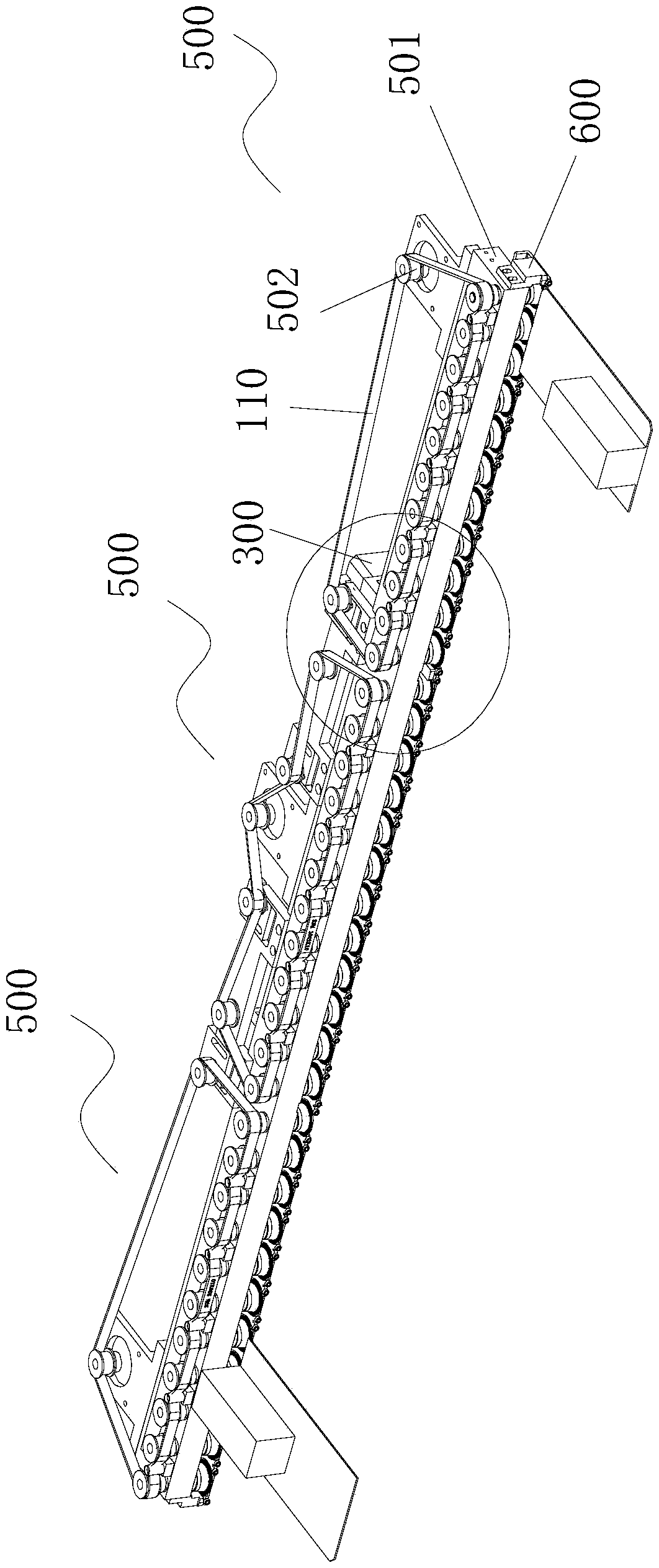
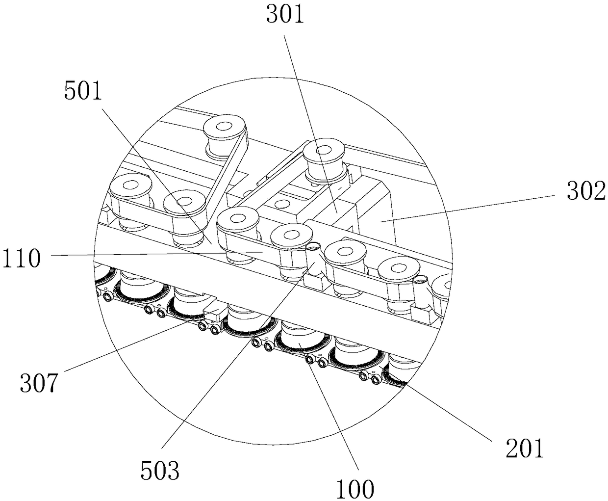
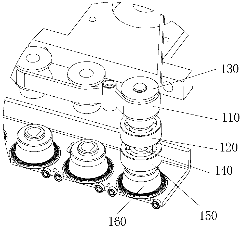
[0097] Such as Figure 1 to Figure 12 As shown, the bare board guide rail of the automatic optical inspection device provided by the present invention includes a plurality of guide rail modules 500 arranged in sequence.

[0098] The guide rail module 500 includes: a guide rail mounting frame 501 on which a guide rail driving motor 502 is installed, and the guide rail driving motor 502 drives the power assembly through the driving belt 110 .

[0099] A guide block 600 is provided on the side of the guid...


PUM


Abstract

The invention provides a naked guide rail of an automatic optic inspection device. The naked guide rail comprises a plurality of guide rail modules which are arranged in sequence; each guide rail module comprises a guide rail mounting frame, a guide rail driving motor, a power assembly, a protection plate structure and a limiting mechanism, wherein the guide rail driving motor is connected onto the guide rail mounting frame; the power assembly is arranged on the guide rail mounting frame in a penetrating manner and the guide rail driving motor is connected with the power assembly through a driving belt; the protection plate structure and the guide rail mounting frame are arranged at interval; the bottom of the power assembly is arranged in the protection plate structure; the limiting mechanism is arranged on the guide rail mounting frame; the limiting mechanism is located between the adjacent guide rail modules. The naked guide rail of the automatic optic inspection device has the following beneficial effects that the structure sis simple and the cost is low; the friction force between a conveying ring and a PCB (Printed Circuit Board) can be increased through conveying teeth on atop surface of the conveying ring and power can be more effectively transmitted to the PCB, so as to drive the PCB to move frontward; a circular-platform-shaped adjusting column can be adaptive to thePCBs with different sizes, so that whole equipment can be adjusteding in a certain range.

Description

technical field [0001] The invention relates to an automatic optical detection device, in particular to a bare board guide rail of the automatic optical detection device. Background technique [0002] The full name of AOI (Automatic Optic Inspection) is automatic optical inspection, which is a device based on optical principles to detect common defects encountered in welding production. AOI is a new type of testing technology emerging, but it is developing rapidly, and many manufacturers have launched AOI testing equipment. During automatic detection, the machine automatically scans the PCB through the camera, collects images, compares the tested solder joints with the qualified parameters in the database, and after image processing, checks out the defects on the PCB, and displays / labels the defects through the display or automatic signs out for repair by the maintenance crew. [0003] Using high-speed and high-precision visual processing technology to automatically detect...

Claims


Application Information

Patent Timeline
Patent Type & Authority Applications(China)
IPC IPC(8): G01N35/02G01N35/04
CPCG01N35/026G01N35/04G01N2035/0486
Inventor 张应时
Owner SHANGHAI WEIXUNSHI AUTOMATION TECH CO LTD
Learn More