Control valve for variable-capacity compressor
A technology for compressors and control valves, which is applied to liquid variable-capacity machinery, variable-capacity pump components, multi-way valves, etc. Reduce the attractiveness and other problems, and achieve the effect of improving the startability and realizing the miniaturization.
- Summary
- Abstract
- Description
- Claims
- Application Information
AI Technical Summary
Problems solved by technology
Method used
Image

Examples
no. 1 approach
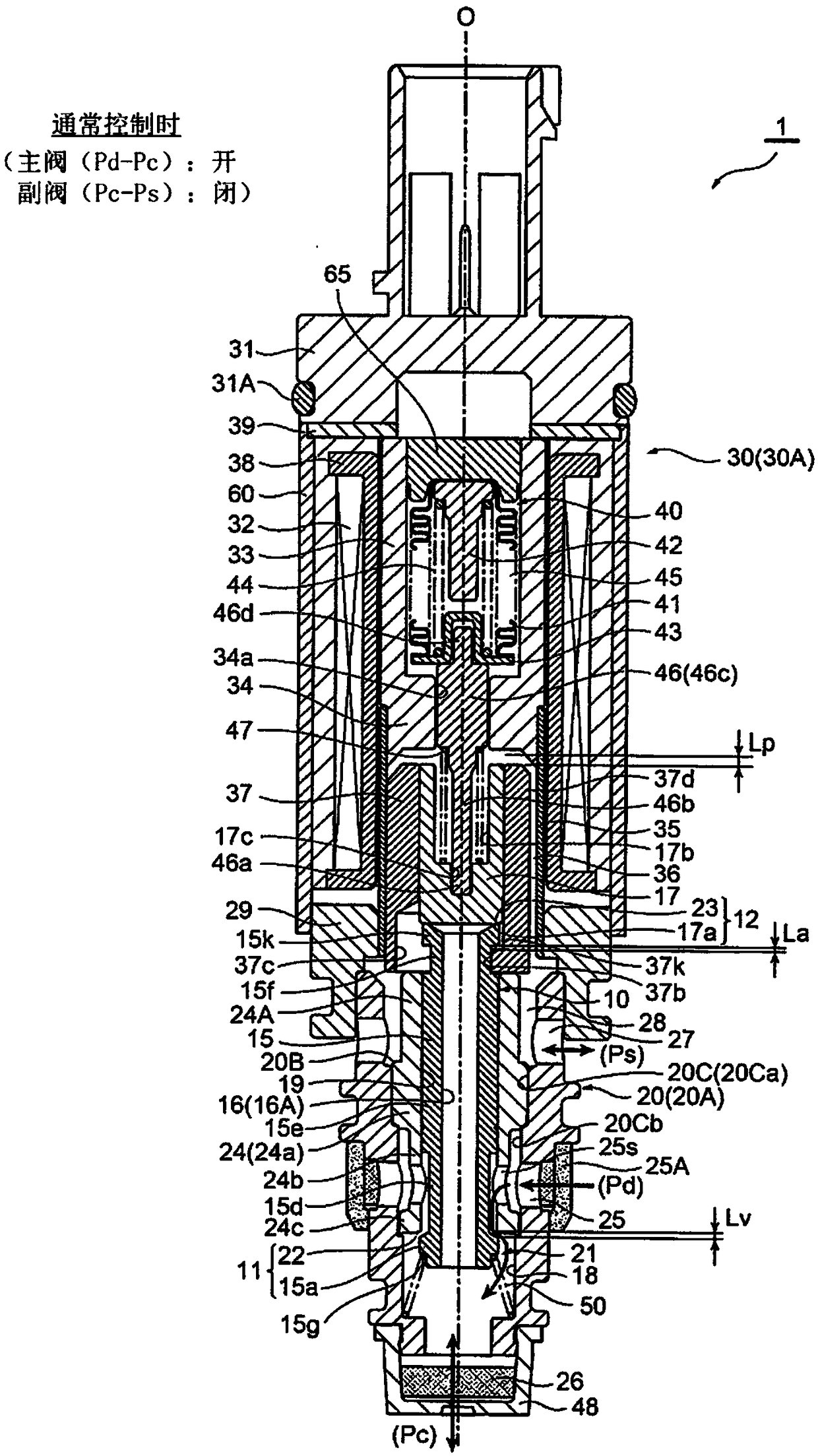
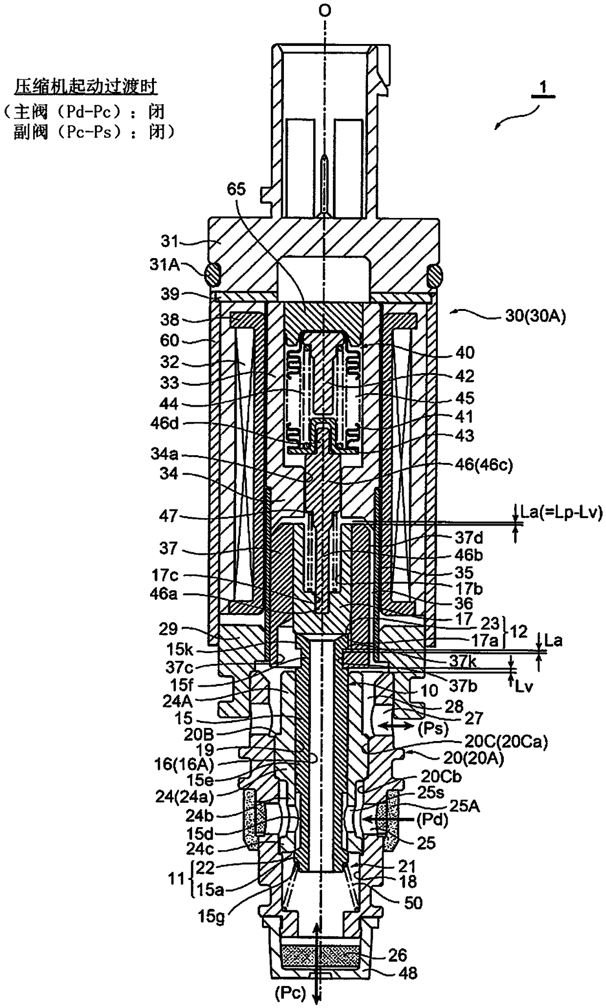
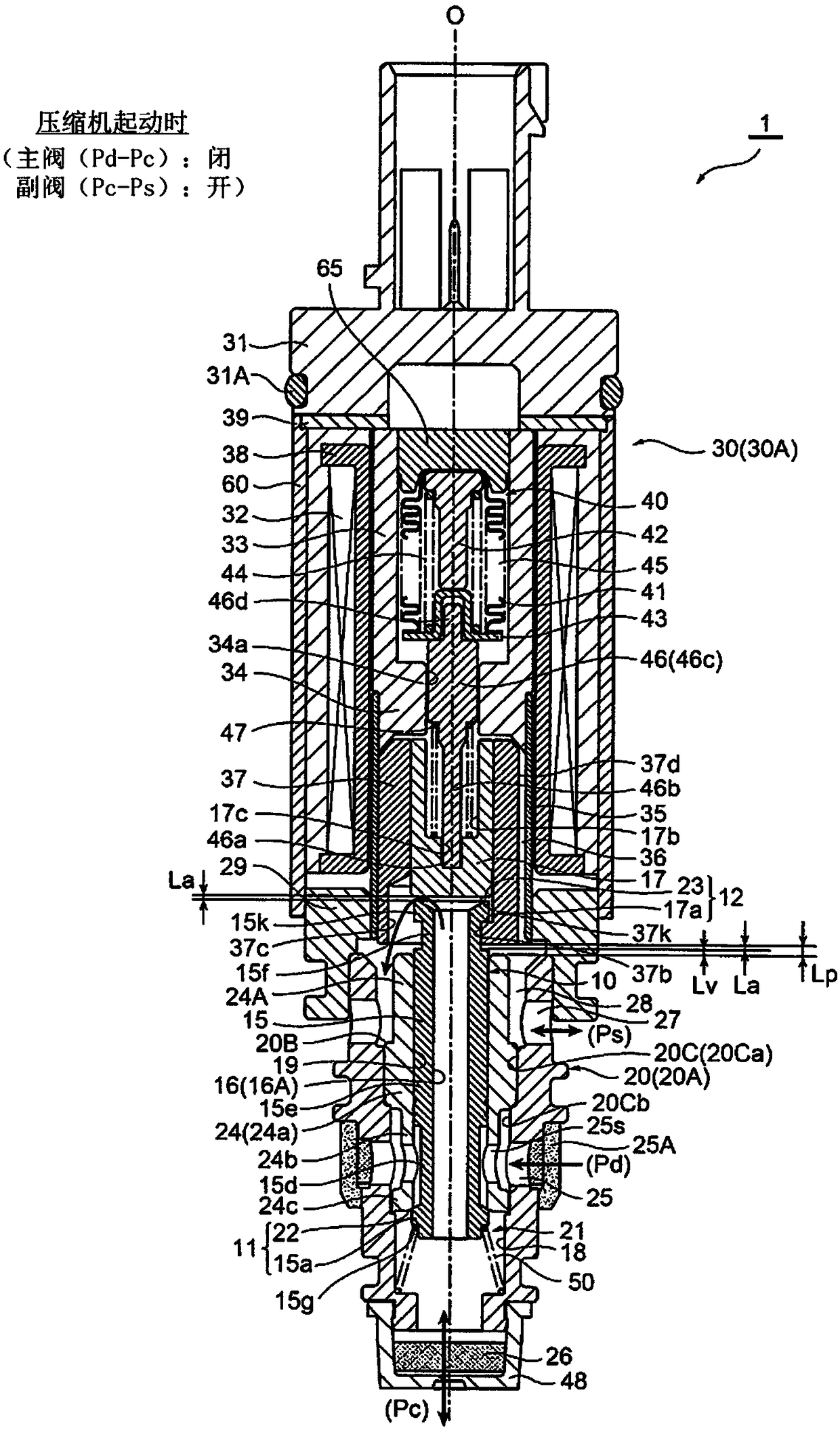
[0049] Figure 1 ~ Figure 3 It is a vertical cross-sectional view showing the first embodiment of the control valve for a variable displacement compressor according to the present invention, figure 1 Indicates that the main valve is open and the auxiliary valve is closed (during normal control), figure 2 Indicates that the main valve is closed and the auxiliary valve is closed (when the compressor starts transition), image 3 Indicates that the main valve is closed and the auxiliary valve is open (when the compressor is started).
[0050] In addition, in this specification, descriptions of positions and directions such as up and down, left and right, front and rear, etc. are indicated in accordance with the drawings for convenience in order to avoid complicating the description, and are not limited to the positions in the state where the compressor is actually assembled. ,direction.
[0051] Also, in each figure, gaps formed between components, spacing distances between c...
no. 2 approach
[0086] Figure 6 ~ Figure 8 It is a vertical cross-sectional view respectively showing the second embodiment of the control valve for a variable displacement compressor according to the present invention, Image 6 Indicates that the main valve is open and the auxiliary valve is closed (during normal control), Figure 7 Indicates that the main valve is closed and the auxiliary valve is closed (when the compressor starts transition), Figure 8 Indicates that the main valve is closed and the auxiliary valve is open (when the compressor is started).
[0087] The control valve 2 of the second embodiment is basically different from the control valve 1 of the above-mentioned first embodiment only in the structure of the plunger 37 and the sub-spool 17 . Therefore, components having the same functions as those in the first embodiment are given the same reference numerals and their detailed descriptions are omitted, and only the above-mentioned differences will be described in detail...
PUM
 Abstract
Description
Claims
Application Information
 - R&D
- Intellectual Property
- Life Sciences
- Materials
- Tech Scout
- Unparalleled Data Quality
- Higher Quality Content
- 60% Fewer Hallucinations
Browse by: Latest US Patents, China's latest patents, Technical Efficacy Thesaurus, Application Domain, Technology Topic, Popular Technical Reports.
© 2025 PatSnap. All rights reserved.Legal|Privacy policy|Modern Slavery Act Transparency Statement|Sitemap|About US| Contact US: help@patsnap.com