

Light emission device and illumination device
A light-emitting device and excitation light technology, which is applied to lighting devices, components of lighting devices, signal devices, etc., can solve the problem that the deflection angle of the light deflecting part increases, the change rate of the optical path length increases, and the diameter of the bright spot of the fluorescent body expands, etc. problem, to achieve the effect of miniaturization
- Summary
- Abstract
- Description
- Claims
- Application Information
AI Technical Summary
Problems solved by technology
Method used
Image

Examples
Embodiment 1
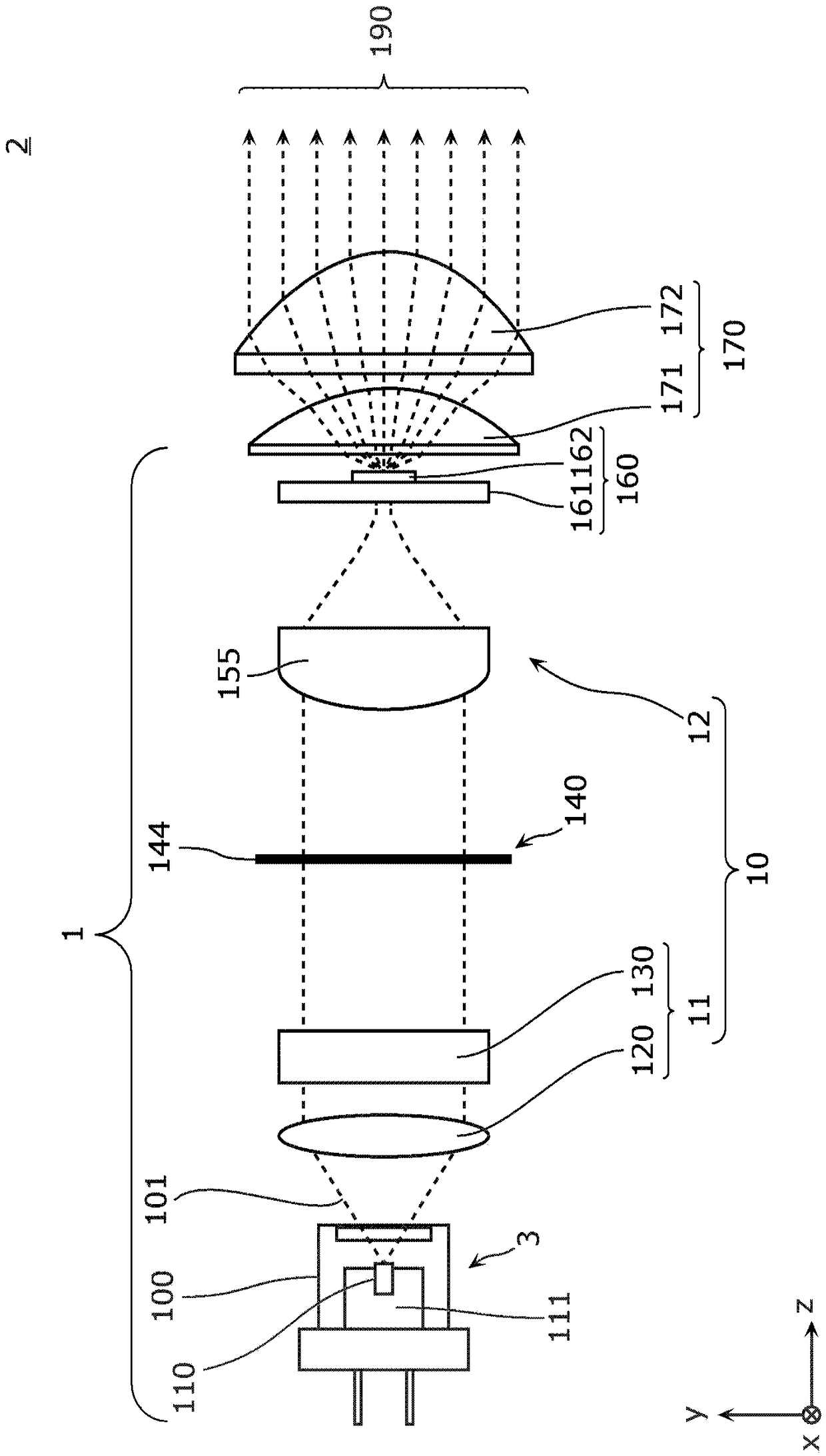
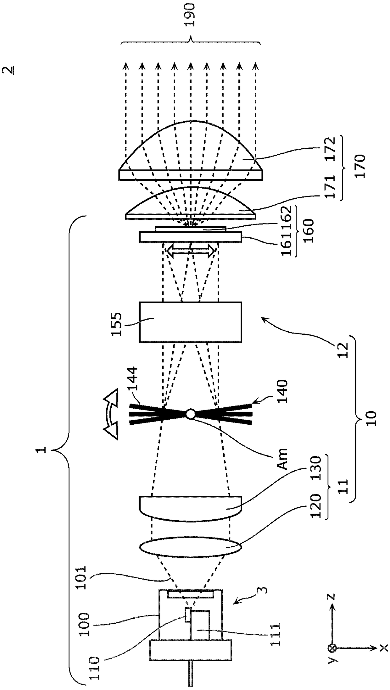
[0048] figure 1 as well as figure 2 It is a side view and a plan view showing the configuration of the simplest optical system of the light emitting device 1 and the lighting device 2 according to the present embodiment, respectively. exist figure 1 as well as figure 2 Here, the optical axis direction of the projection light 190 projected from the illumination device 2 is defined as the z-axis direction, and two directions perpendicular to the optical axis direction and orthogonal to each other are defined as the x-axis direction and the y-axis direction.
[0049] The lighting device 2 related to this embodiment is a device that emits projection light 190, such as figure 1 as well as figure 2 It is shown that the light emitting device 1 and the projection optical system 170 are provided. The light emitting device 1 includes a light source unit 3 , a light deflection unit 140 , a wavelength conversion unit 160 , and a light collection unit 10 .
[0050] The light sourc...
Embodiment 2
[0110] A light-emitting device and an illuminating device according to Example 2 will be described. In this embodiment, the difference from Embodiment 1 is that two semiconductor laser light sources are used. Hereinafter, the present embodiment will be described with reference to the drawings focusing on points of difference from the first embodiment.
[0111] Figure 7 as well as Figure 8 These are a side view and a perspective view showing the optical system configurations of the light emitting device 1a and the lighting device 2a according to the present embodiment, respectively.
[0112] Such as Figure 7 as well as Figure 8 As shown, the lighting device 2 a according to this embodiment includes the light emitting device 1 a and the projection optical system 170 .
[0113] Such as Figure 7 As shown, the light emitting device 1 a includes a light source unit 3 a, a light collecting unit 10 a, a light deflecting unit 140 a, and a wavelength converting unit 160 a. T...
PUM
 Abstract
Description
Claims
Application Information