Solid-state imaging device, method for manufacturing the same, and camera using the same

A technology of a solid-state imaging device and a manufacturing method, which is applied in radiation control devices, image communications, televisions, etc., and can solve problems such as the inability to stably form a transmission layer, the inability to fully guarantee the length of an optical path, and the decline in pixel light-gathering efficiency, to achieve the ultimate goal. Optimizing, reducing manufacturing deviation, and high light-gathering efficiency

Inactive Publication Date: 2007-02-07
PANASONIC CORP
View PDF1 Cites 11 Cited by
  • Summary
  • Abstract
  • Description
  • Claims
  • Application Information

AI Technical Summary

Problems solved by technology

Therefore, there is a problem that, in the structure of the conventional solid-state imaging device, the light-gathering efficiency of the pixels near the periphery decreases, resulting in deterioration of image quality.
In this case, it is difficult to control the formation position with high precision in the structure using the conventional convex microlens
[0011] In addition, in the disclosed method, a method of concentrating light through a transmission layer with a concentric refractive index

Method used


Image

  • Solid-state imaging device, method for manufacturing the same, and camera using the same
  • Solid-state imaging device, method for manufacturing the same, and camera using the same
  • Solid-state imaging device, method for manufacturing the same, and camera using the same

Examples


no. 1 Embodiment approach

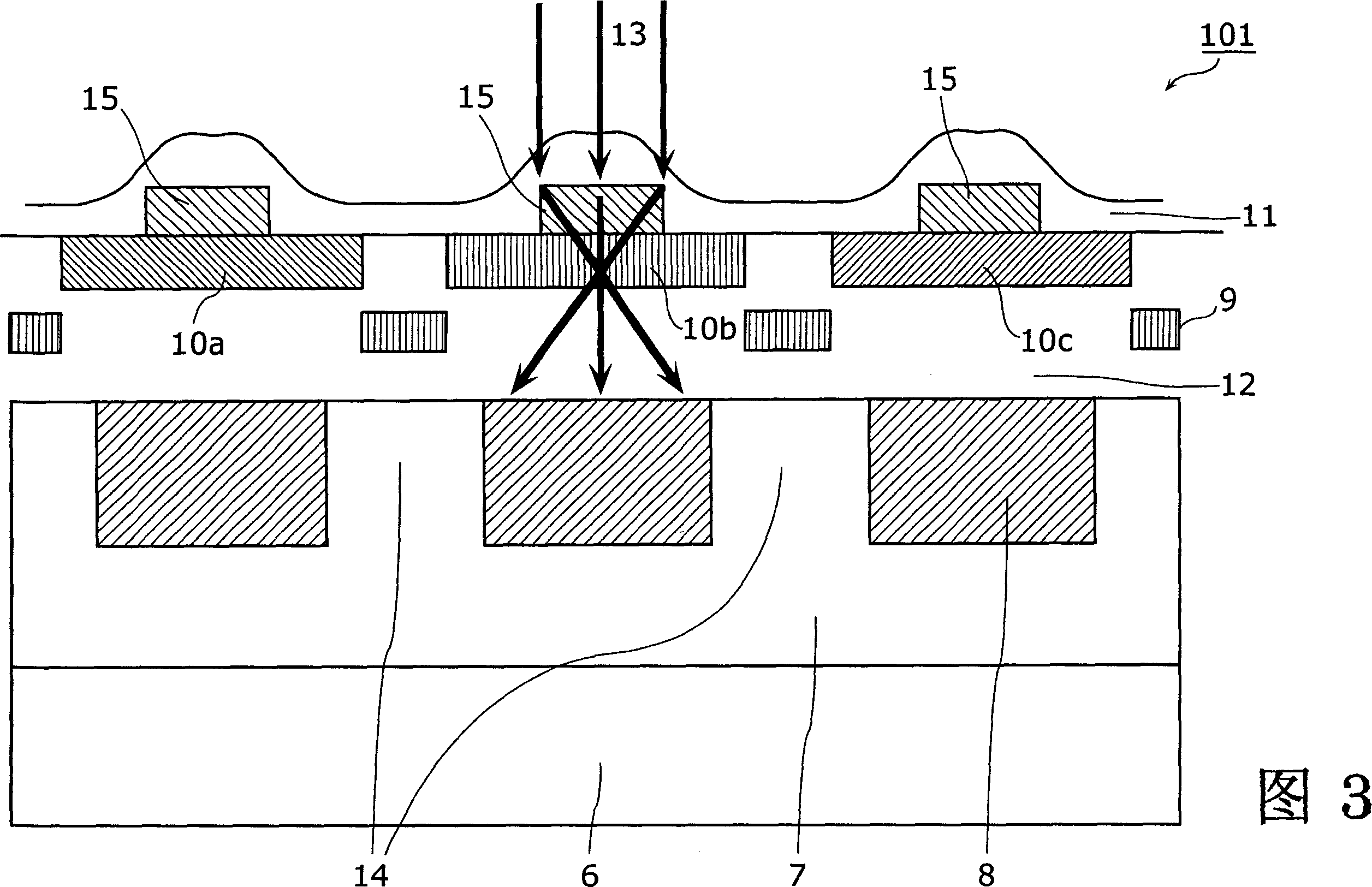
[0087] 3 is a cross-sectional view of a pixel portion of the solid-state imaging device according to the first embodiment of the present invention. In the solid-state imaging device 101 (only three pixels are shown) shown in FIG. 3 , a P-type layer 7 is formed on the N-type layer 6 , and a photodiode 8 is formed in the P-type layer 7 . A light shielding film 9 for shielding light is formed above the isolation region 14 for isolating the photodiodes 8 . In addition, an interlayer insulating film 12, color filters 10a to 10c that transmit only the color light corresponding to each pixel, and the vertically-shaped light of the present invention for condensing incident light 13 are formed on the photodiode 8. The transmissive layer 15 and the lens layer 11 having a concavo-convex shape formed on the upper portion and the periphery of the transmissive layer 15 . In addition, the shape of the transmissive layer 15 may be a cuboid, a cylinder, or the like. In addition, the material...

no. 2 Embodiment approach

[0090] 4 is a cross-sectional view of a pixel portion of a solid-state imaging device according to a second embodiment of the present invention. Here, the difference from the first embodiment is that in the solid-state imaging device 102, the width and height of the vertically shaped transmissive layer of the present invention are determined according to various colors of red (R), green (G) and blue (B). The unit pixels corresponding to the colors are optimally changed, correspondingly, the concavo-convex shape of the lens layer 11 is changed, and the focal lengths relative to the light of each color are respectively set to optimal focal lengths. In particular, since the refractive index of the transmissive layer 15 increases on the short wavelength side and conversely decreases on the long wavelength side, it is necessary to adjust the size of the transmissive layer.

[0091] Among the transmissive layers 15a, 15b, and 15c, the transmissive layer 15a has the smallest width an...

no. 3 Embodiment approach

[0093] Figure 5 (a) to (e) are explanatory diagrams of a method of manufacturing the light-condensing element of the solid-state imaging device according to the third embodiment of the present invention.

[0094] First, if Figure 5 As shown in (a), on the upper part of the base 201 (the color filters 10a to 10c in the above-mentioned first and second embodiments), a film containing SiO? The transmissive layer material 202. Secondly, if Figure 5 As shown in (b), a resist film 203 is formed on the top of the transmissive layer material 202, as Figure 5 As shown in (c), the resist film 203 other than the predetermined portion is removed by photolithography. and further as Figure 5 As shown in (d), the transmissive layer material 202 outside the predetermined area is removed by dry etching. Then if Figure 5 As shown in (e), the use viscosity is higher than that of SiO? The material (BPSG film, TEOS film, benzocyclobutene, polyimide resin, etc.) is used to form the lens lay...


PUM

PropertyMeasurementUnit
Film thicknessaaaaaaaaaa
Refractive indexaaaaaaaaaa

Abstract

In order to implement a solid-state imaging device with high photo-sensitivity that includes a light collecting part which can reduce undesired variations during manufacture and which has high light collection efficiency, the solid-state imaging device includes: a photodiode ( 8 ) which converts incident light ( 13 ) into electric charges; a convex lens layer ( 15 ) which is formed above the photodiode ( 8 ) and through which the incident light is transmitted; and a concavo-convex lens layer ( 11 ) which is formed on and around the lens layer ( 15 ) and which collects the incident light and outputs the incident light to the lens layer ( 15 ). A refractive index of the lens layer ( 15 ) is greater than a refractive index of the lens layer ( 11 ). A thickness and a width of the lens layer ( 15 ) are set to achieve a predetermined focal length for light of a predetermined wavelength range. The lens layer (15) is made of one of a BPSG film, a TEOS film, a benzocyclobuthane and polyimide based resin.

Description

technical field [0001] The present invention relates to a solid-state imaging device mounted on a digital camera or the like. Background technique [0002] Regarding the solid-state imaging device, various technical proposals have been proposed (for example, refer to Patent Document 1). [0003] FIG. 1 illustrates a conventional solid-state imaging device. In this solid-state imaging device 110 , unit pixels 1 are arranged two-dimensionally, each row is selected by a vertical shift register 2 , the row signal is selected by a horizontal shift register 3 , and the color signal of each pixel is output from an output amplifier 4 . The peripheral drive circuit 5 operates the vertical shift register 2 , the horizontal shift register 3 and the output amplifier 4 . [0004] FIG. 2 is a cross-sectional view of a pixel portion of a conventional solid-state imaging device. In the solid-state imaging device 100 (only three pixels are shown in FIG. 2 ), a P-type layer 7 is formed on ...

Claims


Application Information

Patent Timeline
IPC IPC(8): H01L27/146H04N5/335G02B3/00G02B5/18
Inventor 稻叶雄一
Owner PANASONIC CORP
Why Eureka
Try Eureka