
Water purifier and its filter device

A filter element and filter material technology, applied in the field of filter elements, can solve problems such as increased difficulty in assembly, water leakage, and difficulty in balancing the compression of the sealing ring and the feel of rotation

Active Publication Date: 2020-06-16
SHUNDE APOLLO AIR CLEANER
View PDF6 Cites 0 Cited by
  • Summary
  • Abstract
  • Description
  • Claims
  • Application Information

AI Technical Summary

Problems solved by technology

[0007] For the above-mentioned first technology, the number of water stop valves will increase with the increase of the water inlet and outlet on the filter element device, which will lead to more and more cumbersome assembly of the filter element device, which has the disadvantages of low production efficiency and high cost
[0008] For the above-mentioned second technology, since the rotating structure at the end of the filter element device is fixed by screws, and the torque of the screws is difficult to control, it is difficult to balance the compression amount of the sealing ring on the rotating structure and the rotating feel, and there are Water Leakage Hazard
[0009] For the above-mentioned third technology, setting a rotating structure on the filter seat will complicate the structure of the filter seat and increase the difficulty of assembly
[0010] In addition to the above-mentioned several defects, the existing filter element device also has deficiencies such as water leakage, incomplete filtration, and complicated disassembly and assembly operations.

Method used


Image

  • Water purifier and its filter device
  • Water purifier and its filter device
  • Water purifier and its filter device

Examples


Embodiment 1

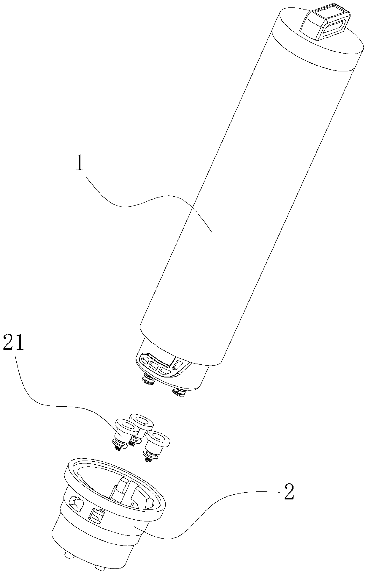
[0076] Such as figure 1 As shown, the embodiment of the present invention provides a filter element device, which mainly includes a filter element body 1 and a base 2, the base 2 is provided with a base flow channel connected with an external flow channel, the filter element body 1 is provided with a body flow channel, and the filter element body 1 The first end is screwed into the base 2 and the flow channel of the main body is aligned with the flow channel of the base. There is an automatic water locking component 21 between the main body flow channel and the base flow channel. The filter body 1 and the base 2 control the automatic water locking component through relative rotation 21 is opened and closed to realize the connection and disconnection of the main body flow channel and the base flow channel.

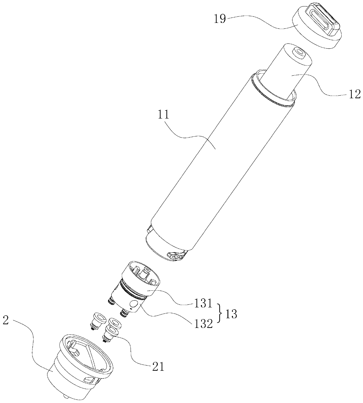
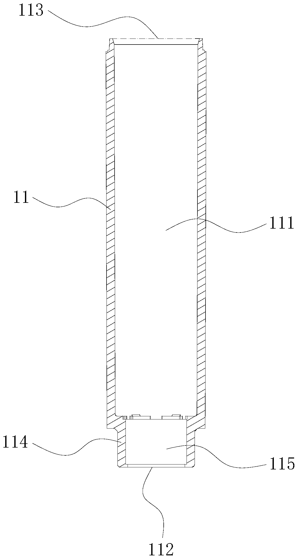
[0077] Specifically, such as Figure 2 to Figure 4 As shown, the filter element body 1 includes a housing 11, a filter material 12 and a water-stop assembly 13. The housin...

Embodiment 2

[0090] Such as Figures 17 to 19 As shown, the only difference between this embodiment and Embodiment 1 is that the filter element device in this embodiment adopts a double-channel structure, that is, it includes an inlet channel for accessing tap water and an outlet channel for discharging filtered water. , there is no sewage discharge flow channel for discharging filtered waste water, therefore, the first water inlet flow channel 14a is formed between the inner side wall of the housing 11 and the outer side wall of the filter material 12, and the flow channel cavity of the filter material 12 is the first outlet. The water channel 14b; the water channel in the water channel 131 includes a second water inlet channel 15a and a second water outlet channel 15b, which are combined into an inner cavity that runs through the rotating shaft 1311, the connecting column 1312 and the first limiting column 1316, and The second water inlet channel interface 151 and the second water outlet...

Embodiment 3

[0092] Such as Figures 20 to 22 As shown, the difference between this embodiment and Embodiment 1 is that there is no sealing disk 1313 between the rotating shaft 1311 of the water distribution member 131 and the connecting column 1312 in this embodiment, instead, a partition is provided in the installation cavity 111. The dividing plate 116 of the water-distributing member 131 and the water-retaining member 132, the center of the dividing plate 116 is provided with a through hole, and the rotating shaft 1311 of the water-distributing member 131 passes through the through hole and is rotatably connected with the rotating hole and rotating hole 1321 of the water-retaining member 132; and , the first protrusion 171 is disposed on the partition plate 116 , and the first protrusion 171 and the first sliding groove 172 of the water retaining member 132 form a sliding limit structure. Of course, the first protrusion 171 of the partition 116 and the first sliding groove 172 of the w...


PUM


Abstract

The invention provides a filter element unit. The filter element unit comprises a water stopping assembly and an automatic water locking assembly, wherein the water stopping assembly can control supply and non-supply of water to a filtering cavity, thereby being able to prevent residual water in the filtering cavity from flowing out in the disassembling process of the filter element unit; the automatic water locking assembly can control supply and non-supply of water between the filter element unit and an external pipe, thereby being able to prevent a water flow in the external pipeline from overflowing in the disassembling process of the filter element unit; thus, a two-way water-sealing structure composed of the water stopping assembly and the automatic water locking assembly completelyeradicates the hidden danger of water leakage, and guarantees that the filter element unit always maintains dry and tidy after disassembled. In addition, the water stopping assembly adopts a manner ofsupply and non-supply of water from a side surface, so an assembly structure is simplified; the smoothness of a water distribution member and a water blocking member during relative rotation is improved; resistance during rotation is reduced; and good hand feeling of operation control is achieved. In addition, the invention also provides a water purifier equipped with the above-mentioned filter element unit. The water purifier has the advantages of no water leakage, no water channeling, conveniently-replaced filter element, etc.

Description

technical field [0001] The invention relates to the technical field of filter elements, in particular to a water purifier and a filter element device thereof. Background technique [0002] As water purifiers are becoming more and more popular among consumers, consumers have higher and higher requirements for product experience. Among them, the filter element device that automatically seals water when it is disassembled has attracted the most attention from consumers. [0003] Various automatic water sealing filter element devices have appeared in the prior art, mainly including the following technologies: [0004] 1. A water stop valve is installed on the filter element device to realize water connection and water cutoff; [0005] Two, the end of the filter element device is provided with a rotating structure, and the water can be connected and cut off through misalignment; [0006] Third, a rotating structure is set on the filter seat, and the water can be connected and c...

Claims


Application Information

Patent Timeline
Patent Type & Authority Patents(China)
IPC IPC(8): B01D29/31B01D35/30B01D61/02B01D61/14
CPCB01D29/31B01D35/30B01D61/025B01D61/145
Inventor 陈建建刘社军何坤垣禤开华皮小春
Owner SHUNDE APOLLO AIR CLEANER
Learn More