Belt slipping detecting method of belt conveyor and belt slipping detecting device of detecting method

A belt conveyor, belt slip technology, applied in the direction of conveyor control device, conveyor, conveyor objects, etc., can solve the problems of complex structure, power consumption, material accumulation, etc., to achieve high response frequency, low power consumption, failure Accurate effect of alarm signal

Inactive Publication Date: 2019-03-05
辛鹏
View PDF5 Cites 5 Cited by
  • Summary
  • Abstract
  • Description
  • Claims
  • Application Information

AI Technical Summary

Problems solved by technology

However, during the operation of the conveyor, due to the difference in the state and moisture content of the material, sometimes the belt will be crushed, causing the belt to slip and not work
This situation will cause the machine head motor to drive the machine head drum to run idly, and consume electric energy for no reason.
But it is important to note that if the belt stalls to cause material to accumulate, in different situations, different serious consequences may occur
[0003] At present, technical personnel have proposed detection and alarm devices for belt slippage. The detection and judgment methods are different, and the product structures are also different, but most of them have complex structures and high costs.

Method used


Image

  • Belt slipping detecting method of belt conveyor and belt slipping detecting device of detecting method
  • Belt slipping detecting method of belt conveyor and belt slipping detecting device of detecting method
  • Belt slipping detecting method of belt conveyor and belt slipping detecting device of detecting method

Examples


Embodiment 1

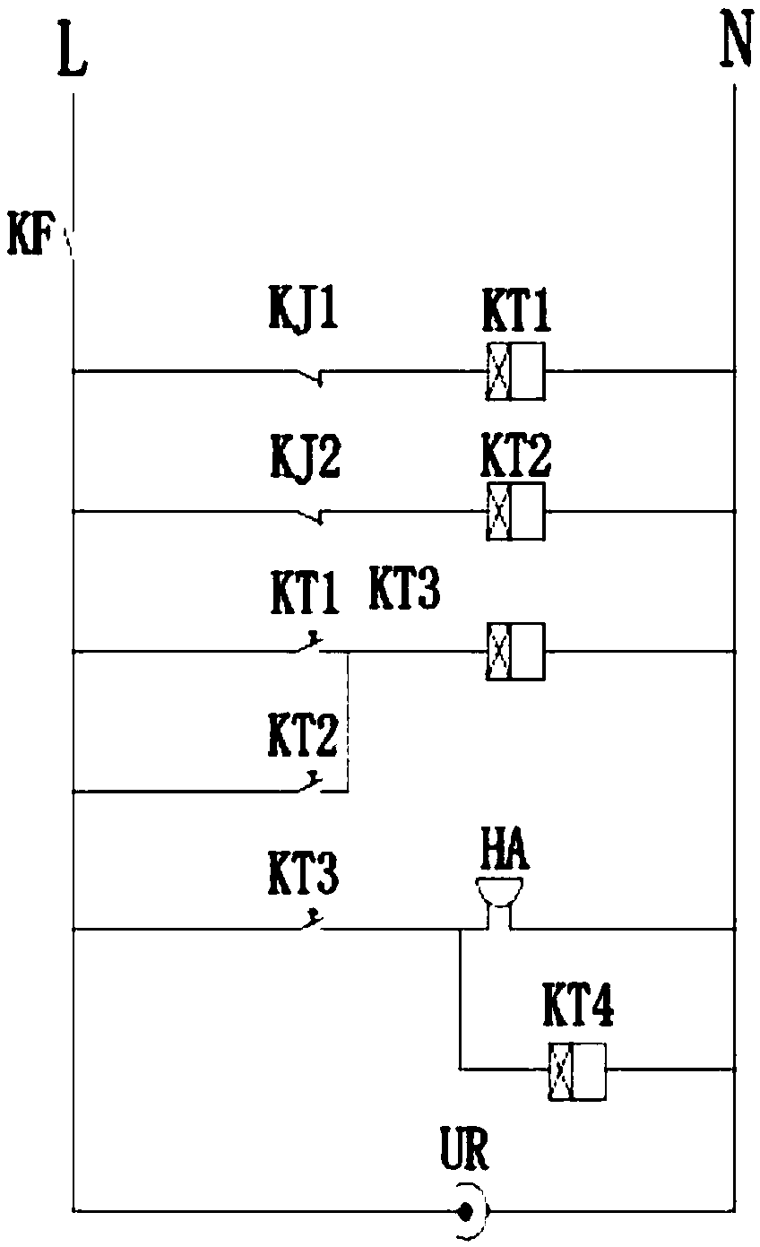
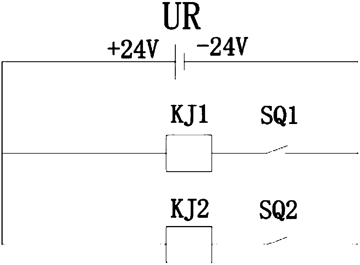
[0026] The belt slip detection method of the belt conveyor described in this embodiment adopts at least two groups of detection switches connected in parallel, each parallel circuit is connected with an intermediate relay, and a time relay is connected in the control circuit of each intermediate relay, and the completion The output switch signals of two groups of detection switches are detected within the time period t, and the output contacts of the time relay are connected to an alarm circuit.

[0027] In the belt slipping detection method of the belt conveyor, the detection switch adopts a Hall proximity switch, a travel switch, an infrared sensor switch or a capacitance sensor switch, and whether the output switch signal of the detection switch reflects the running state of the drive drum.

[0028] The belt slipping detection method of the belt conveyor of the present invention uses the conduction delay and power-off delay characteristics of the time relay to set a time per...

Embodiment 2

[0031] see figure 1 , figure 2 , Figure 4 . A belt slipping detection device, comprising a detection switch, a DC24V intermediate relay, a time relay, and an alarm. The detection switches are at least two groups, powered by a switching power supply, and an intermediate relay is connected to each group of detection switch circuits. A time relay is connected in an intermediate relay control circuit, the control switch of the time relay is connected in parallel, and a time delay relay control circuit is connected, and the control switch output signal of the time delay relay is connected to an alarm or a belt conveyor power-off control circuit . The block used in conjunction with the detection switch is set on the inner edge of one end of the belt conveyor drive roller, and the detection switch is fixed on the belt conveyor frame through the mounting support. The detection switch and the detection block The blocks correspond to and are distributed on the contour line of the ...

Embodiment 3

[0036] see Figure 1 ~ Figure 4 . The belt slipping detection device described in this embodiment includes a belt conveyor power-off control circuit, and the belt conveyor power-off control circuit includes a control relay and an intermediate relay, and the drive coil of the control relay is connected in parallel with the alarm. The control output signal of the control relay is connected to the intermediate relay in the power-off control circuit of the belt conveyor. Using the power-off delay characteristic of the time relay, the belt conveyor motor is powered off to achieve the control function.

[0037] image 3 KM is the intermediate relay of the motor control circuit.

[0038]In the belt slip detection device of the present invention, a baffle plate is fixedly installed on the inner edge of the belt drive drum, and a proximity switch is installed on the support of the drive drum, and the distance between the proximity switch and the baffle plate is 10-20mm. The time re...


PUM


Abstract

The invention relates to detection for belt slipping of a belt conveyor. A belt slipping detecting method of the belt conveyor includes the following steps that firstly, a roller and a support of thebelt conveyor are fixedly provided with detecting switches and stopping blocks; secondly, with rotating of the transmission roller rotates by one circle as a period, a time quantum t is set; and thirdly, output signals of the two detecting switches are monitored in real time, if the output signals sent by the detecting switches are not detected within the time quantum t, it is judged that belt slipping occurs. A belt slipping detecting device comprises the detecting switches, intermediate relays, time relays and an alarming device. Power is supplied to the detecting switches through a switching power source; one intermediate relay is connected in a loop of each detecting switch, and one time relay is connected in a control loop of each intermediate relay; control switches of the time relays are connected in parallel, and are connected into a control loop of a time delay relay; and a control output signal of the time delay relay is connected with the alarming device or a power-off control loop of the belt conveyor.

Description

technical field [0001] The invention relates to a detection method and a detection control device for belt slippage of a belt conveyor. Use the proximity switch to detect the running status of the conveyor drive roller. Background technique [0002] Belt conveyors are widely used in material transfer in fields such as agriculture, chemical industry, electric power, coal and mines. In order to prevent safety accidents caused by conveyor failures, technicians designed deviation protection and pull rope switch devices. However, during the operation of the conveyor, due to the difference in the state and moisture content of the material, sometimes the belt will be crushed, causing the belt to slip and not work. This situation will cause the machine head motor to drive the machine head drum to run idly, consuming electric energy for no reason. But it is important to note that if the belt stalls to cause material to accumulate, in different situations, different serious consequ...

Claims


Application Information

Patent Timeline
Patent Type & Authority Applications(China)
IPC IPC(8): B65G43/04
CPCB65G43/04B65G2203/04
Inventor 辛鹏
Owner 辛鹏
Why Eureka
Try Eureka