Disc brake and vehicle

A technology of disc brakes and brake blocks, applied in the direction of brake types, axial brakes, brake actuators, etc., can solve the problems of complex layout structure, low braking comfort, hydraulic oil leakage, etc., and achieve the layout method Flexible, highly functional integration, small footprint effect

Active Publication Date: 2019-03-05
BYD CO LTD
View PDF17 Cites 8 Cited by
  • Summary
  • Abstract
  • Description
  • Claims
  • Application Information

AI Technical Summary

Problems solved by technology

[0002] In the traditional hydraulic or pneumatic braking system, there are obvious disadvantages such as complex gas-liquid pipeline, difficult maintenance, complex layout structure, slow dynamic response of braking, and low braking comfort performance.
For example, in the hydraulic braking system, the brake pedal will rebound and vibrate when the anti-lock braking system operates, which affects the braking comfort performance
For another example, since the brake pedal mechanism is directly connected with the brake transmission device and the brake actuator, the impact force generated when the vehicle collides will be directly transmitted to the cab through the brake system, which seriously affects the safety performance of the car.
As another example, the conventional hydraulic braking system uses components of the conventional hydraulic braking system such as the vacuum brake booster, the brake master cylinder, and the oil reservoir that are relatively large in size, so it not only has complex structure and assembly, but also has a large volume. , Difficult maintenance, and because the system is equipped with hydraulic brake lines and brake fluid connected to the corresponding components, it is necessary to replace the hydraulic oil regularly and regularly check whether there is a problem of hydraulic oil leakage

Method used


Image

  • Disc brake and vehicle
  • Disc brake and vehicle
  • Disc brake and vehicle

Examples


Embodiment Construction

[0025] Specific embodiments of the present disclosure will be described in detail below in conjunction with the accompanying drawings. It should be understood that the specific embodiments described here are only used to illustrate and explain the present disclosure, and are not intended to limit the present disclosure.

[0026] In the present disclosure, unless stated otherwise, the used orientation words such as "left and right" generally refer to the left and right of the drawing direction of the corresponding drawings, and the use of these orientation words is only for the convenience of description. It should not be considered as a limitation of the present disclosure.

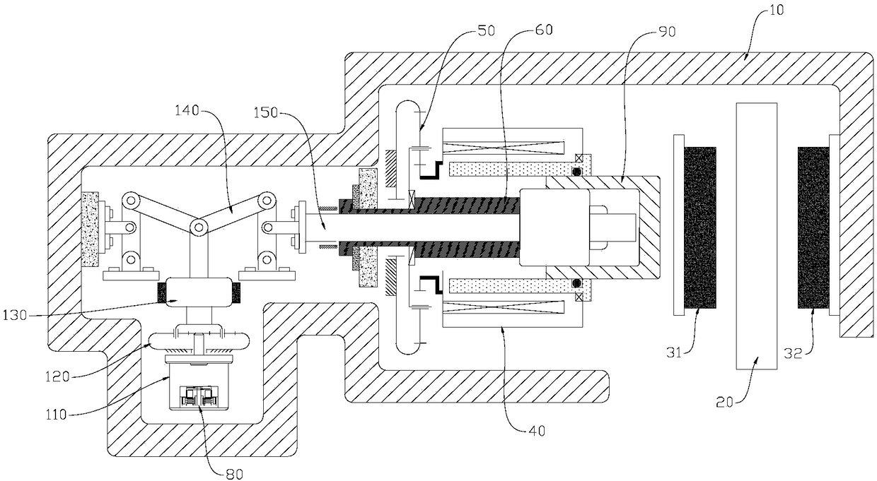
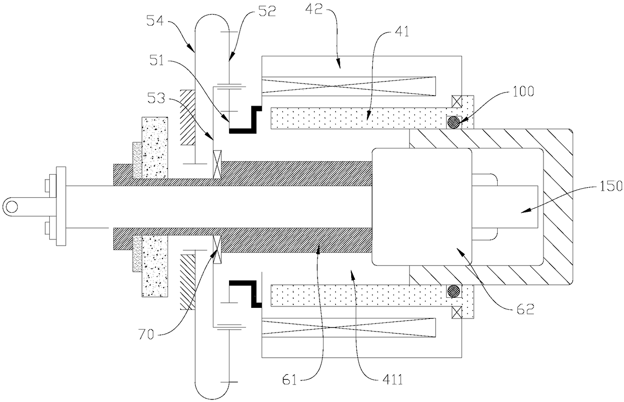
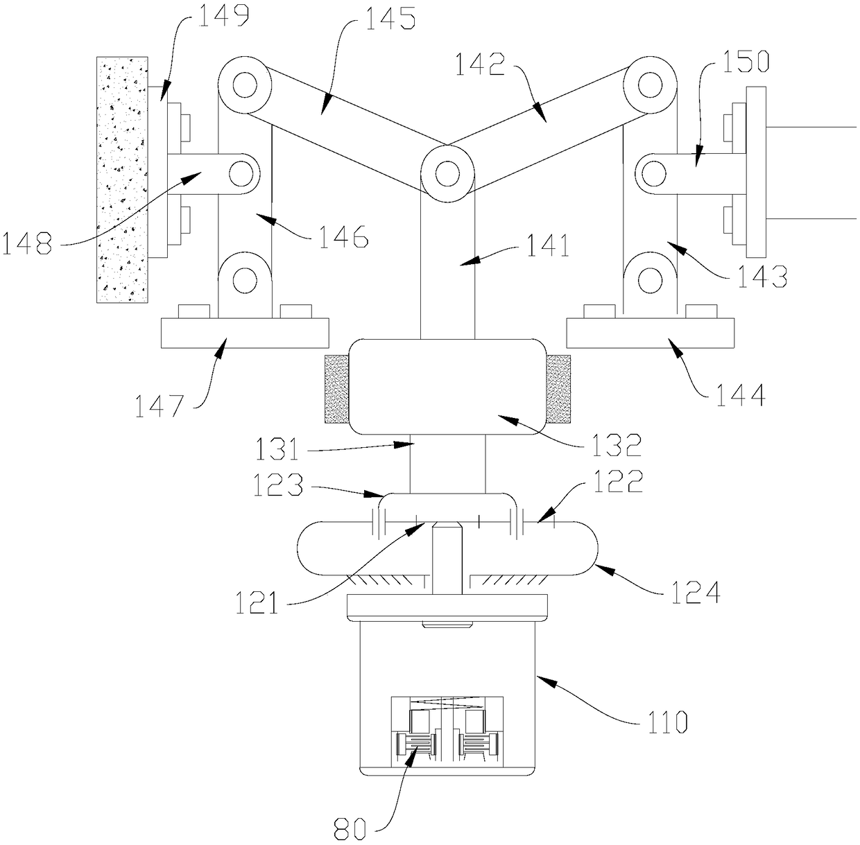
[0027] According to one aspect of the present disclosure, there is provided a disc brake, such as figure 1 with Figure 5 As shown, it includes a brake caliper body 10, a first brake block 31, a service brake unit and a parking brake unit. The first brake block 31 and the second brake block 32 are respe...


PUM


Abstract

The invention relates to a disc brake and a vehicle. The disc brake comprises a brake caliper body, a first brake block, a driving braking unit and a parking braking unit, wherein the parking brakingunit comprises a parking motor, a parking screw rod mechanism, a lever mechanism and a push rod; the parking motor drives the push rod to axially move through the parking screw rod mechanism and the lever mechanism in sequence, so that the push rod is enabled to push the first brake block to move so as to compress the brake disc; and the lever mechanism is used for transmitting output force of theparking screw rod mechanism to the push rod. In the brake disclosed by the invention, the driving braking unit and the parking braking unit are arranged so that the brake can achieve two functions ofdriving braking and parking braking at the same time, the function integration level is high, the structure is compact, and the occupied space is small; and compared with hydraulic or pneumatic parking, the braking response is faster, and the safety is better; and in addition, by arranging the lever mechanism, the arrangement mode of all parts in the brake is more flexible, and the structure is more compact.

Description

technical field [0001] The present disclosure relates to the field of brakes, in particular, to a disc brake and a vehicle. Background technique [0002] In the traditional hydraulic or pneumatic braking system, there are obvious disadvantages such as complex gas-liquid pipeline, difficult maintenance, complex layout structure, slow dynamic response of braking, and low braking comfort performance. For example, in the hydraulic braking system, when the anti-lock braking system operates, the brake pedal will produce rebound vibration, which affects the braking comfort performance. For another example, since the brake pedal mechanism is directly connected with the brake transmission device and the brake actuator, the impact force generated when the vehicle collides will be directly transmitted to the cab through the brake system, seriously affecting the safety performance of the car. As another example, the conventional hydraulic braking system has complex structure and assemb...

Claims


Application Information

Patent Timeline
Patent Type & Authority Applications(China)
IPC IPC(8): F16D55/228F16D65/16F16D121/24F16D125/22
CPCF16D55/228F16D65/16F16D2121/24F16D2125/22
Inventor 郑祖雄
Owner BYD CO LTD
Why Eureka
Try Eureka