Hot blast stove running in high pressure

A hot blast stove and high-pressure technology, which is applied in the direction of furnace, furnace cooling, furnace charge, etc., can solve the problems of small reserved space in the working chamber of the furnace body, reduce the strength of the workpiece, and slow cooling speed, so as to prevent external air from entering the furnace body , Prevent oxidation-reduction reaction, prevent oxidation effect

Inactive Publication Date: 2019-03-05
张跃
View PDF7 Cites 1 Cited by
  • Summary
  • Abstract
  • Description
  • Claims
  • Application Information

AI Technical Summary

Problems solved by technology

[0003] The existing brazing furnace generally maintains a low pressure state of 0.01~0.1MPa in the furnace, but due to poor air tightness, gas will enter the furnace during the actual process
[0004] Secondly, when the existing workpiece is brazed in a high temperature environment, if the workpiece is made of an easily oxidizable material, it will be easily oxidized at high temperature. Once the workpiece is oxidized, the strength of the workpiece will be reduced.
[0005] Thirdly, in the existing heating furnace, the furnace body is usually divided into multiple cavity modules, such as preheating area, working area, drying area, cooling area, etc., so that the reserved space for the working chamber of the furnace body is small, which is not suitable for for large workpieces
[0006] In addition, the existing furnace body cools the workpiece through the fan, and the cooling speed is slow, which greatly reduces the work efficiency

Method used


Image

  • Hot blast stove running in high pressure
  • Hot blast stove running in high pressure

Examples


Embodiment 1

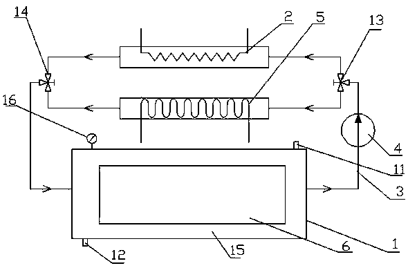
[0031] like figure 1 Shown: a high-pressure operating hot blast stove, including a furnace body 1, the outer shell of the furnace body 1 is wrapped by a water-cooled jacket. The furnace body is provided with an air inlet 11 and an air outlet 12, the air inlet 11 is provided with an air inlet valve, and the air outlet 12 is provided with an exhaust valve.

[0032] The outside of the furnace body 1 is provided with a heating body 2 and a cooler 5. The heating body 2 and the cooler 5 are connected to the inlet and outlet of the furnace body 1 through a circulation pipeline 3. The heating body 2 and the cooler 5 are connected to two ends of a circulation pipeline. On the branch road, that is, the heating branch and the cooling branch, the front electric three-way valve 13 and the rear electric three-way valve 14 are arranged at the junction of the two ends of the heating branch and the cooling branch, to switch between the hot air channel and the cold air channel, And the valve o...

Embodiment 2

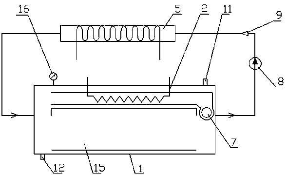
[0040] like figure 2 Shown: the difference with embodiment 1 is that the hot air circulation is an internal circulation mode. The inner tank of the furnace body 1 is divided into a working cavity 15 and a heating zone, and the working cavity 15 and the heating zone are two different chambers, and the two are communicated with each other. A heating body 2 is arranged in the heating zone.

[0041] The workpiece is placed in the working chamber 15 . The furnace body 1 is provided with a main fan 7, and the impeller of the main fan 7 is a centrifugal impeller. The motor, motor shaft and impeller of the main fan 7 are all arranged in the body of heater 1, and the motor and the motor shaft are wrapped by a water-cooled jacket. The outside of the body of furnace 1 is provided with a quick cooling fan 8 and a cooler 5, and the quick cooling fan 8, the cooler 5 and the working chamber 15 are connected through pipelines, and the pipeline between the quick cooling fan 8 and the coole...

Embodiment 3

[0046] The difference from Embodiment 2 is that a heating body is provided in the working chamber of the furnace body, and the heating body and the working chamber are connected through a partition, and the heating body communicates with the working chamber.

[0047] Other structures are with embodiment 2.


PUM


Abstract

A hot blast stove running in high pressure comprises a stove body. A workpiece in the stove body is brazed under the condition that the pressure is 0.1 MPa or above. According to the hot blast stove running in the high pressure, on the one hand, the workpiece can be in an oxygen-free environment, and outside air is prevented from entering the stove body; and on the other hand, the workpiece can beprevented from oxidizing.

Description

technical field [0001] The invention relates to the technical field of hot blast stoves, in particular to a hot blast stove operating at high pressure. Background technique [0002] The existing furnace heating methods are usually vacuum heating, induction heating, salt bath heating, etc. Among them, the vacuum heating technology refers to the gas state in a designated space that is lower than the ambient atmospheric pressure, that is, the number density of gas molecules in the space is lower than the molecular number density of the atmospheric pressure in the area. In vacuum technology, the degree of vacuum is commonly used to measure the thinness of space gas in a vacuum state. The higher the pressure, the lower the vacuum; the lower the pressure, the higher the vacuum. Vacuum heating technology mainly heats by thermal radiation. When the above-mentioned heating methods are used to heat a large workpiece, the workpiece will be heated unevenly, and the structure will be ...

Claims


Application Information

Patent Timeline
Patent Type & Authority Applications(China)
IPC IPC(8): F24H3/04F24H9/18F24H9/20B23K3/00B23K1/008
CPCB23K1/008B23K3/00B23K3/04B23K3/053B23K3/085F04D25/06F04D29/5806F04D29/582F24H3/0405F24H9/1863F24H9/2071F27B9/028F27B9/30F27B9/34F27B2009/305F27D1/0043F27D1/18F27D1/1858F27D1/1866F27D7/02F27D9/00F27D99/0001F27D99/0073F27D2009/0005F27D2009/0037F27D2009/0075F27M2003/05H02K9/19
Inventor 张跃
Owner 张跃
Why Eureka
Try Eureka