RF overlap impedance measuring device and manufacturing and measuring method thereof

A technology of impedance measurement and radio frequency, which is applied in the direction of frequency measurement devices, measurement devices, and measurement of electrical variables, etc. It can solve the problems of high requirements for instruments, inability to realize frequency sweep measurement of impedance, unsuitable measurement of radio frequency impedance, etc., and achieve high measurement accuracy , Expand the measurable frequency range, and the effect of wide impedance measurement range

Active Publication Date: 2019-03-05
CSR ZHUZHOU ELECTRIC LOCOMOTIVE RES INST
View PDF11 Cites 1 Cited by
  • Summary
  • Abstract
  • Description
  • Claims
  • Application Information

AI Technical Summary

Problems solved by technology

[0007] In view of this, the object of the present invention is to provide a radio frequency lap impedance measurement device and its production and measurement method, to solve the problem that the existing impedance measurement method cannot realize the frequency sweep measurement of impedance, which is not suitable for measuring the radio frequency lapped in the actual system. Impedance, and technical issues requiring high instrumentation

Method used


Image

  • RF overlap impedance measuring device and manufacturing and measuring method thereof
  • RF overlap impedance measuring device and manufacturing and measuring method thereof
  • RF overlap impedance measuring device and manufacturing and measuring method thereof

Examples


Embodiment 1

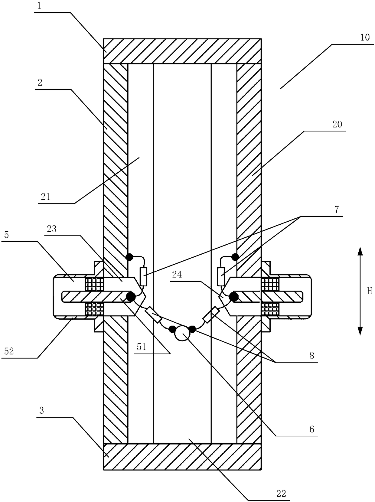
[0059] as attached figure 2 , 3 , Shown in 4 and 5, the specific embodiment of a kind of radio frequency lap impedance measurement device, comprises:

[0060] The cylinder body 20 , the top plate 1 located at the upper part of the cylinder body 20 , and the bottom plate 3 located at the lower part of the cylinder body 20 , an inner cavity is formed between the cylinder body 20 , the top plate 1 and the bottom plate 3 . The cylinder 20 further includes a shell 2 made of conductive material, and a cover plate 4 made of non-conductive material and matched with the shell 2;

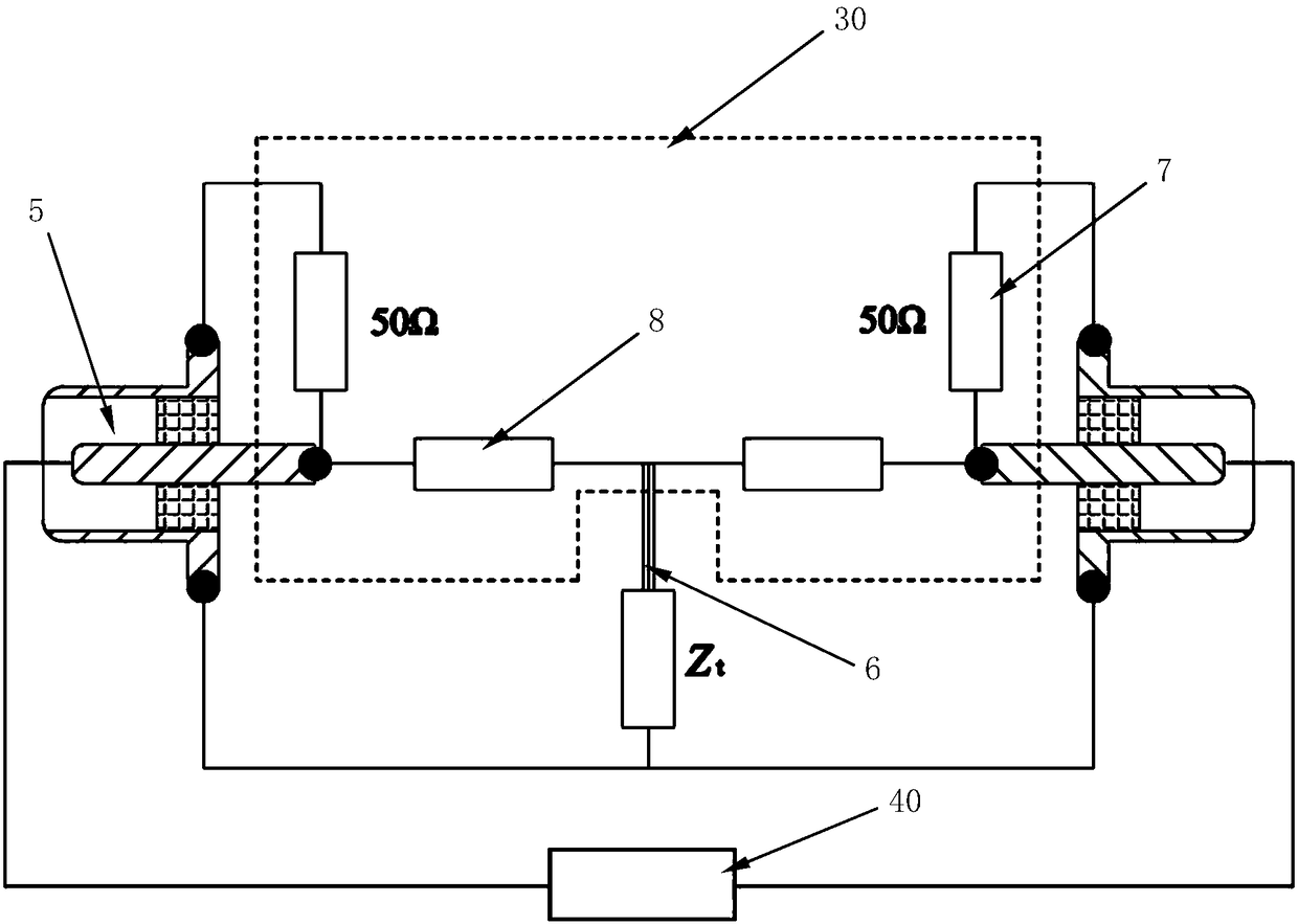
[0061] One end is located in the inner cavity, and the other end is connected to the external test equipment 40 after passing through the housing 2, and is symmetrically arranged on the two test interfaces 5 on the opposite sides of the housing 2;

[0062] One end is located in the inner cavity, and the other end passes through the cover plate 4 and is connected to the external measured lap joint system 50...

Embodiment 2

[0070]A specific embodiment of a radio frequency bonding impedance measurement system based on the device described in Embodiment 1, the system includes: an impedance measuring device 10 and a measured bonding system 50 connected to the impedance measuring device 10, and the measured bonding system 50 includes Cabinet 9 and lap bar 12. The impedance measuring device 10 is connected to the cabinet 9 through the measuring clamp 6, and the bottom of the cabinet 9 is provided with an insulating pad 11, and the housing 2 of the impedance measuring device 10 is connected to the reference ground 13 through the bottom plate 3, and the cabinet 9 is connected to the ground through the lap bar 12 at the same time. Connect to reference ground 13.

[0071] as attached Image 6 As shown, the tested bonding system 50 that is bonded with the impedance measuring device 10 simulates a size of 150 × 150 × 100mm 3 Cabinet 9 by 0.6 x 20 x 100mm 3 The grounding system of the flat bonding bar 12 ...

Embodiment 3

[0073] In order to design an impedance measuring device 10 that can measure the RF lap impedance in an actual system, this embodiment combines the device structure shown in Embodiment 1, and after comprehensively analyzing the performance of the existing measuring device, proposes an application RF bonding impedance measurement setup in real system. Wherein, the cylinder body 20 of the impedance measuring device 10 is mainly composed of two parts, one part is a metal shell 2 made of brass in the main body, and the other part is a cover plate 4 made of Bakelite material located on the opposite side of the metal shell 2 . A specific embodiment of the manufacturing method of the RF lap impedance measuring device as described in Embodiment 1, comprising the following steps:

[0074] S11) Select a square material made of conductive material, and set the mounting holes 23 for the test interface 5 on two opposite sides of the square material; the housing 2 made of brass adopts a 25×2...


PUM


Abstract

The invention discloses an RF overlap impedance measuring device and a manufacturing and measuring method thereof. The device comprises a cylinder, a top plate and a base plate; an inner cavity is formed among the cylinder, top plate and base plate; the cylinder comprises a conductive casing and a non-conductive cover plate cooperated with the casing; two test interfaces are symmetrically arrangedin the side part, opposite to each other, of the casing symmetrically, one end of each interface is positioned in the inner cavity, and the other end of the interface penetrates out of the casing andis then connected with test equipment; one end of a measuring chuck is positioned in the inner cavity, and the other end of the clamping chuck penetrates the cover plate and is then connected with atested overlap system; a measuring circuit accommodated in the inner cavity comprises a matching resistor and a disconnecting resistor; one end of each of two matching resistor is connected to the casing, and the other end of the matching resistor is connected with the corresponding test interface; and one end of each disconnecting resistor is connected with the corresponding test interface, and the other end of the disconnecting resistor is connected to one end of the measuring chuck. Thus, the technical problems that a present impedance measuring manner cannot realize impedance sweep measurement, is not suitable for measuring the overlap RF impedance of a practical system, and has high requirements for instruments are solved.

Description

technical field [0001] The invention relates to the technical field of electronic and electrical measurement, in particular to a radio frequency lap impedance measurement device and its manufacturing and measurement methods. Background technique [0002] There may be a potential difference between the metal casings (or frames) of different equipment, components and components in the electrical and electronic system, and this potential difference is often one of the causes of electromagnetic interference. The purpose of lapping is to provide a uniform structural surface and low impedance path for the flow of current, so as to avoid the potential difference between the two metal parts connected to each other. Bonding can be used between metal chassis of equipment, between equipment chassis and ground plane, between signal return wires and ground wires, and between cable shields and ground wires. The lap impedance is usually an important index to measure the lap effect, so in ...

Claims


Application Information

Patent Timeline
Patent Type & Authority Applications(China)
IPC IPC(8): G01R27/04G01R23/04
CPCG01R23/04G01R27/04
Inventor 闫光临杨德勇支永健石煜朱柄全闵建军范祝霞周伟
Owner CSR ZHUZHOU ELECTRIC LOCOMOTIVE RES INST
Why Eureka
Try Eureka