Calibration method and system for data sampling

A calibration method and sampling point technology, applied in signal transmission system, electrical signal transmission system, analog/digital conversion and other directions, can solve the problems of time deviation, large synthesis error of zero sequence current, consumption, etc., to save power consumption, data The effect of reducing and reducing the amount of calculation

Active Publication Date: 2019-03-05
北京智云芯科技有限公司
View PDF5 Cites 15 Cited by
  • Summary
  • Abstract
  • Description
  • Claims
  • Application Information

AI Technical Summary

Problems solved by technology

Even if the two acquisition devices perform strict time synchronization with a cycle of one second, that is, the time of the two acquisition devices is strictly synchronized at the beginning of each second, and the synchronization error is 0, but due to the influence of ±20PPM frequency deviation, in this second At the end, the time of each device will have a deviation of ±20us compared with the standard time, resulting in a cumulative time deviation of up to 40us between the two acquisition devices
The time deviation of 40us will cause a relatively large synthesis error in the synthesized zero-sequence current, which seriously affects the accuracy of fault judgment
Each time synchronization requires data acquisition equipment to consume additional energy. For power-sensitive data acquisition equipment, frequent time synchronization is a huge power consumption burden

Method used


Image

  • Calibration method and system for data sampling
  • Calibration method and system for data sampling
  • Calibration method and system for data sampling

Examples


specific Embodiment approach

[0110] see Figure 10 , is the method flowchart of Embodiment 7 of the present invention. Embodiment 7 of the present invention is based on Embodiment 6. In step S805, the positions of two adjacent actual sampling points and the weight coefficients between the current ideal sampling point I respectively A specific implementation of the calculation method, including S1001-S1003:

[0111] S1001, rounding the position of the actual sampling point J0 corresponding to the current ideal sampling point I;

[0112] S1002, subtracting the value of the rounded part from the position of the actual sampling point J0 corresponding to the current ideal sampling point I, to obtain the weight coefficient between the current ideal sampling point I and another actual sampling point J1, which is denoted as Q1;

[0113] S1003, subtracting Q1 from 1 to obtain a weight coefficient between the current ideal sampling point I and the calculated actual sampling point J0 corresponding to the current id...


PUM


Abstract

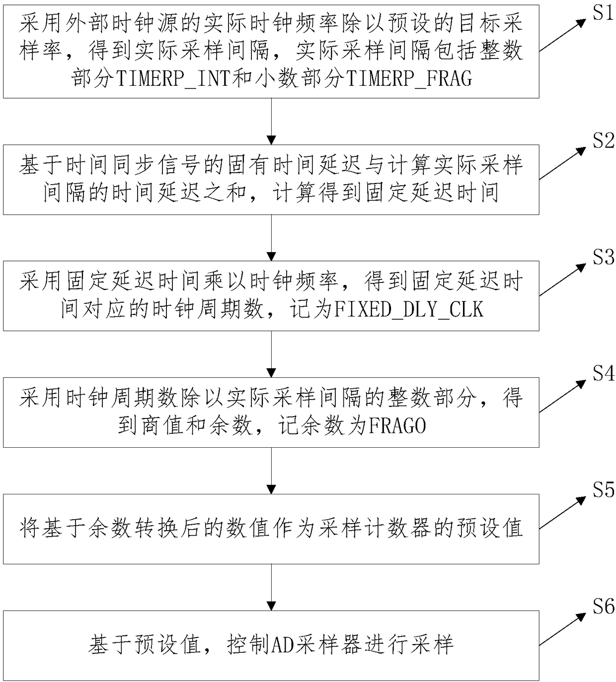
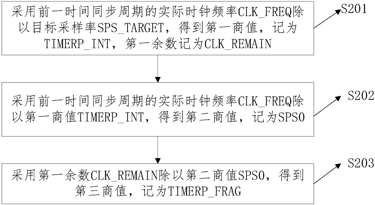
The invention discloses time synchronization and calibration methods and systems for data sampling. The method comprises the following steps that an actual clock frequency of an external clock sourceis divided by a preset target sampling rate to obtain an actual sampling interval, wherein the actual sampling interval comprises an integer part TIMER_INT and a decimal part TIMER_FRAG; fixed delay time is calculated according to a sum of an inherent time delay of a time synchronization signal and a time delay of calculating the actual sampling interval; a clock cycle number corresponding to thefixed delay time is obtained by multiplying the fixed delay time by the clock frequency; the clock cycle number is divided by the integer part of the sampling interval to obtain a quotient value and aremainder, and the remainder is denoted as FRAGO; the remainder is taken as an initial count value of first counting of a sampling counter in a current time synchronization period; and based on the initial count value, an AD sampler is controlled to carry out first sampling. According to the method, the calculation amount of post-calibration can be reduced.

Description

technical field [0001] The invention belongs to the technical field of data sampling, and in particular relates to a calibration method and system for data sampling. Background technique [0002] The global power backbone network is a three-phase AC power system with a frequency of 50Hz or 60Hz. In order to ensure the stable operation of the power system, it is necessary to accurately measure the voltage and current of the three-phase AC. At present, the main measurement technology is computer-based digital measurement technology, that is, through voltage and current sensors (or transformers), high-voltage, high-current signals (that is, the primary signal of the power system) are converted into small-amplitude signals suitable for measurement. The voltage or current signal (that is, the secondary signal of the power system) is then sent to the ADC (Analog-to-Digital Converter) to be quantized and converted into a digital signal, and the collected signal is converted and ca...

Claims


Application Information

Patent Timeline
Patent Type & Authority Applications(China)
IPC IPC(8): H03M1/50G01R31/00
CPCH03M1/50G01R31/00Y04S10/52
Inventor 霍晓芳白彩云
Owner 北京智云芯科技有限公司
Why Eureka
Try Eureka