Aquaculture production feed mixing device with automatic filling function

An automatic filling and mixing device technology, which is applied to mixers, feeds, mixers, etc. with rotating stirring devices, can solve the problems of incomplete unloading, long mixing cycle, waste, etc., to reduce the load of the motor and change the structure Defects, the effect of increasing the stirring rate

Pending Publication Date: 2019-03-08
HUZHOU JIUZHI AUTOMATION TECH
View PDF0 Cites 6 Cited by
  • Summary
  • Abstract
  • Description
  • Claims
  • Application Information

AI Technical Summary

Problems solved by technology

[0006] The present invention provides a feed mixing device for production and breeding with automatic filler, which aims to solve the biggest disadvantage of the existing vertical feed mixing equipment, which is that the mixing uniformity is low, which can only reach about 87%, and the mixing cycle is long , the production efficiency is low, and the output is about 500-1500 kg per hour. Another disadvantage of this vertical mixing equipment is that the unloading is not complete. There are often remaining materials at the bottom of the barrel, which will cause waste. There is a horizontal feed mixer. Compared with the vertical feed mixer, the horizontal feed mixing equipment has the disadvantages of large volume, large area occupation, and high price. It is also troublesome to operate and requires regular inspection and maintenance. The problem

Method used


Image

  • Aquaculture production feed mixing device with automatic filling function
  • Aquaculture production feed mixing device with automatic filling function
  • Aquaculture production feed mixing device with automatic filling function

Examples


Embodiment Construction

[0027] In order to make the object, technical solution and advantages of the present invention clearer, the present invention will be further described in detail below in conjunction with the accompanying drawings and embodiments. It should be understood that the specific embodiments described here are only used to explain the present invention, not to limit the present invention.

[0028] In describing the present invention, it should be understood that the terms "length", "width", "upper", "lower", "front", "rear", "left", "right", "vertical", The orientation or positional relationship indicated by "horizontal", "top", "bottom", "inner", "outer", etc. are based on the orientation or positional relationship shown in the drawings, and are only for the convenience of describing the present invention and simplifying the description, rather than Nothing indicating or implying that a referenced device or element must have a particular orientation, be constructed, and operate in a ...


PUM


Abstract

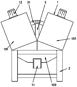
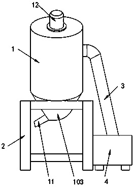
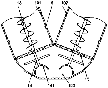
The invention discloses an aquaculture production feed mixing device with an automatic filling function and belongs to the technical field of feed mixing equipment. The key point of the technical scheme is that the aquaculture production feed mixing device with the automatic filling function comprises a feed mixing bin and a feed mixing bin bracket fixed at the bottom of the feed mixing bin; the feed mixing bin consists of a first mixing bin, a second mixing bin and a combining bin; and the first mixing bin and the second mixing bin are both hollow cylinders. By designing the feed mixing bin in a V shape formed by two crossed mixing bins and arranging the combining bin which is used for communicating the two mixing bins at the bottom, the advantages of a vertical mode and a horizontal modeare combined, so that the feed mixing bin realizes higher mixing efficiency in the case of small floor area; as materials have certain inclined angles in the mixing bin, the stirring area during mixing is larger, smaller gravity force is borne; and therefore, the load of a motor can be reduced; under coordination of a conical material mixing auger, the stirring speed can be increased, so that thematerial mixing speed is higher and the efficiency is higher.

Description

technical field [0001] The invention relates to the field of feed mixing equipment, in particular to a feed mixing device with automatic filler for production and breeding. Background technique [0002] In the field of animal husbandry, both livestock and poultry need to be fed with feed, but the feed that needs to be fed is different in different growth stages of livestock and poultry, and some additives are often added to the feed, which is beneficial to the growth and development of livestock and poultry. Health, and additives generally need to be added to the feed and mixed together. In some large breeding plants, the feed mixer is a mechanical device that uses mechanical force and gravity to mix two or more materials evenly. During the mixing process, the contact surface area of ​​the materials can also be increased, and two or more materials can be mixed together. [0003] There are two types of feed mixers currently on the market. [0004] 1. One is the vertical fee...

Claims


Application Information

Patent Timeline
IPC IPC(8): B01F7/04B01F7/08B01F15/00B01F15/02A23N17/00
CPCA23N17/007B01F27/2321B01F27/192B01F27/706B01F27/721B01F35/43B01F35/715B01F35/71775
Inventor 沈强俞升飏俞峰
Owner HUZHOU JIUZHI AUTOMATION TECH
Why Eureka
Try Eureka