Crystallizer cooling device and cooling method thereof

A technology of cooling device and crystallizer, applied in the field of metal casting equipment, can solve the problems of complex structure of cooling device, uneven cooling water flow rate, uncontrollable cooling process, etc., to achieve cooling effect, simple processing method and long service life. Effect

Pending Publication Date: 2019-03-08
XIAN BRANCH ELECTRIC TECH
View PDF12 Cites 3 Cited by
  • Summary
  • Abstract
  • Description
  • Claims
  • Application Information

AI Technical Summary

Problems solved by technology

Its disadvantages include: 1. Adopting non-standard design, the structure of the cooling device is complex and difficult to process; 2. The cooling device adopts an integral welding method, which is easy to deform during the welding process and has welding stress, which leads to easy deformation during use and short life; 3. Each cooling circuit is connected in series or in parallel, resulting in uneven cooling water flow rate and dead angle; 4. The cooling process is uncontrollable

Method used


Image

  • Crystallizer cooling device and cooling method thereof
  • Crystallizer cooling device and cooling method thereof
  • Crystallizer cooling device and cooling method thereof

Examples


Embodiment 1

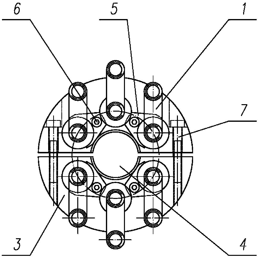
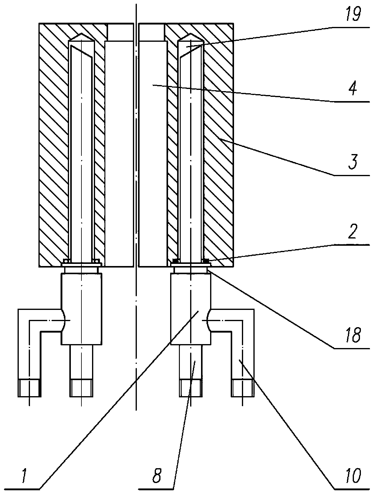
[0035] reference figure 1 , figure 2 with Figure 5 , Including a cooling jacket 3 sleeved on the crystallizer, the cooling jacket 3 is provided with a plurality of blind cooling holes 19, the cooling pipe 1 is assembled on the blind cooling hole 19 through a sealing fixing sleeve 9; the cooling pipe 1 includes a water inlet pipe 8. The sealing fixing sleeve 9 and the water return pipe 10 are sleeved on one end of the water inlet pipe 8 and connected to it by welding. The other end of the water inlet pipe 8 extends into the blind cooling hole 19 and enters There is a backwater gap between the water pipe 8 and the blind cooling hole 19; the backwater pipe 10 is fixedly connected to the side wall of the sealing fixing sleeve 9 by welding and is connected to the backwater gap through the sealing fixing sleeve 9; in order to ensure the cooling effect of the mold, The backwater gap in this embodiment is 1.5-3mm; the cooling device of this embodiment includes a plurality of cooling t...

Embodiment 2

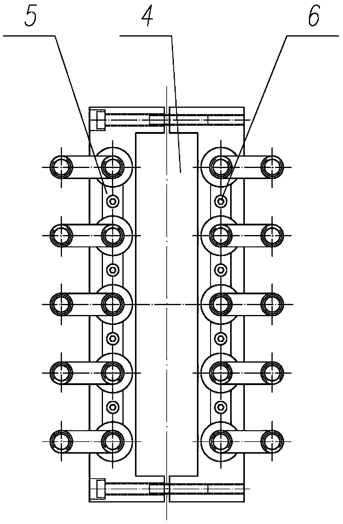
[0058] The difference between this embodiment and Embodiment 1 is that the cooling jacket 3 is a cooling jacket with a rectangular cross-sectional shape, and the mold assembly hole 4 is a mold assembly hole with a rectangular cross-sectional shape. The inside of the cooling jacket 3 is evenly distributed along its central axis on both sides of the mold assembly hole 4. The pressing member 5 is preferably a strip-shaped pressing plate, and the elongated pressing plate is provided at a position corresponding to each slot 18 A recessed structure adapted to the slot 18, the fastener 6 is preferably a bolt or a screw, and the pressure plate and the cooling pipe are further compressed and fixed by the fastener 6.

[0059] The cooling device of the present invention has a simple structure, strong applicability, and good cooling uniformity, and the cooling pipe adopts a local welding method, so that the cooling device is not easily deformed during use, and has a long service life while ac...


PUM


Abstract

The invention discloses a crystallizer cooling device and a cooling method thereof. The crystallizer cooling device comprises a cooling jacket arranged on a crystallizer in a sleeved manner, and a cooling pipe is assembled on a cooling blind hole through a seal fixing sleeve; the cooling pipe comprises a water inlet pipe, the seal fixing sleeve and a water return pipe, and the seal fixing sleeve is arranged at one end of the water inlet pipe in the sleeved manner, and hermetically connected with the water inlet pipe; the other end of the water inlet pipe extends into the cooling blind hole, and a water return clearance is reserved between the other end of the water inlet pipe and the cooling blind hole; the water return pipe is fixedly connected with the side wall of the seal fixing sleeve, and communicates with the water return clearance through the seal fixing sleeve; the water inlet pipe communicates with a main water inlet pipe through an electric regulating valve, and the water return pipe communicates with a main water return pipe; an outlet pipeline of the water return pipe is further provided with a temperature measuring element, and the temperature measuring element and the electric regulating valve are connected with a PID temperature control regulating unit electrically; and closed-loop control over return water temperature can be achieved by the PID temperature control regulating unit through the electric regulating valve.

Description

Technical field [0001] The invention belongs to the technical field of metal casting equipment, and specifically relates to a crystallizer cooling device and a cooling method thereof. Background technique [0002] Continuous casting (including horizontal, upward, downward continuous casting and semi-continuous casting) is an advanced casting method. Its principle is to continuously pour molten metal into a special metal mold called a mold, and solidify The shelled castings are continuously pulled out from the other end of the mold, and castings of any or specific length can be obtained. It can realize continuous casting of bars, pipes and plates. Among them, the cooling device of the mold is very critical, which directly determines the structure and performance of the cast slab. [0003] The traditional mold cooling device adopts an integrated design according to the specifications and shapes of the casting billet. Generally, after the cavity is welded from copper plates, the wat...

Claims


Application Information

Patent Timeline
Patent Type & Authority Applications(China)
IPC IPC(8): B22D11/055
CPCB22D11/055
Inventor 赵吉泽吕静茹
Owner XIAN BRANCH ELECTRIC TECH
Why Eureka
Try Eureka