Efficient cutting waste scrap collecting machining machine tool
A high-efficiency technology for processing machine tools, which is applied in the direction of metal processing machinery parts, metal processing, metal processing equipment, etc., can solve the problems that cannot be cleaned in time, and iron filings stay on the machine tool, so as to save extra power output and high linkage efficiency , high linkage effect
- Summary
- Abstract
- Description
- Claims
- Application Information
AI Technical Summary
Problems solved by technology
Method used
Image
Examples
Embodiment 1
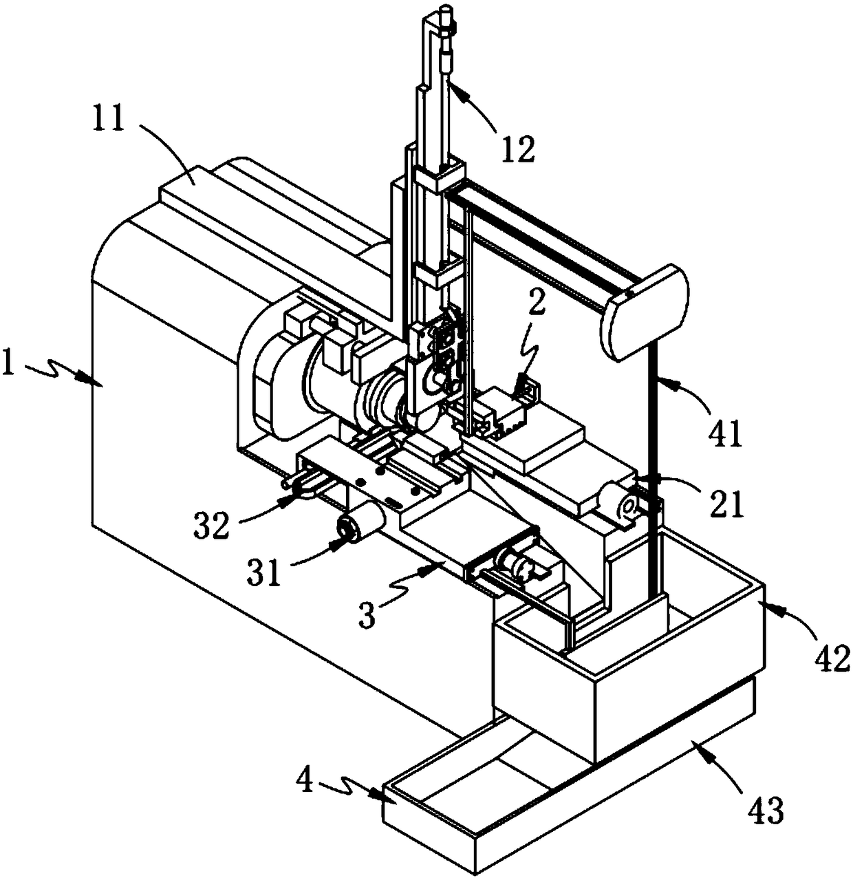
[0063] Such as figure 1 As shown, a processing machine tool for efficient collection of cutting waste, including:
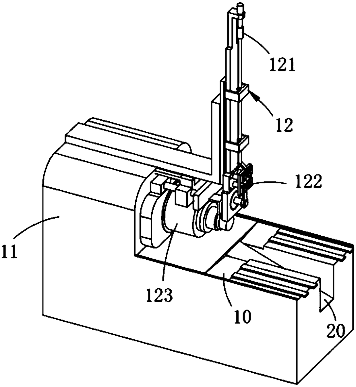
[0064]A feeding assembly 1, which includes a lathe 11 and a mounting part 12 arranged on the lathe 11;
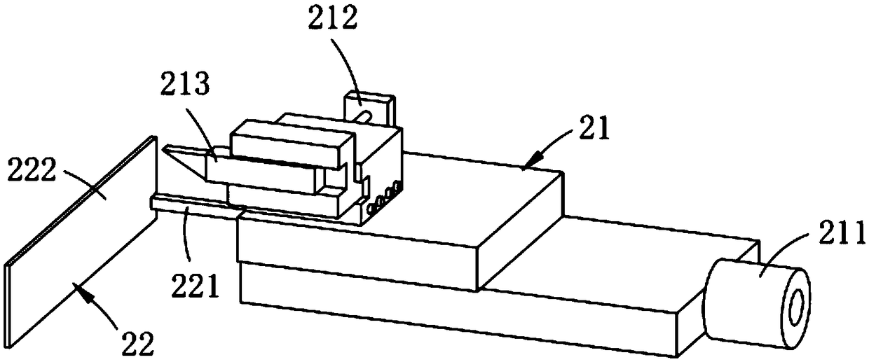
[0065] A processing assembly 2, the processing assembly 2 is slidably arranged on the lathe 11, which includes a first sliding member 21 and a first pushing member 22 fixedly connected to the end of the first sliding member 21;
[0066] The chamfering assembly 3, the chamfering assembly 3 is arranged on the other side of the processing assembly 2, it includes a second sliding piece 31 that is slidably arranged on the lathe 11, and is arranged at the front end of the second sliding piece 31 The material receiving member 32 and the second pushing member 33 fixedly arranged on the rear end of the second sliding member 31; and
[0067] The output assembly 4, the output assembly 4 includes a linkage 41 connected to the installation part 12, a first output part 42...
Embodiment 2
[0114] Such as Figure 9 As shown, the components that are the same as or corresponding to those in the first embodiment are marked with the corresponding reference numerals in the first embodiment. For the sake of simplicity, only the differences from the first embodiment will be described below. The difference between this embodiment two and embodiment one is:
[0115] further, such as Image 6 As shown, the discharge plate b432 is set obliquely downward.
[0116] It is worth mentioning that the discharge plate b432 is set obliquely, in order to allow most of the iron filings to be collected at the end of the discharge box b431.
[0117] work process:
[0118] First, install the workpiece on the clamping and pushing unit 122, the horizontal pushing unit 121 drives the clamping and pushing unit 122 to move downwards, and then the clamping and pushing unit 122 pushes the workpiece to the carrier unit 123, and moves the first slider 21 to chamfer the workpiece At this time, t...
PUM
 Abstract
Description
Claims
Application Information
 - R&D Engineer
- R&D Manager
- IP Professional
- Industry Leading Data Capabilities
- Powerful AI technology
- Patent DNA Extraction
Browse by: Latest US Patents, China's latest patents, Technical Efficacy Thesaurus, Application Domain, Technology Topic, Popular Technical Reports.
© 2024 PatSnap. All rights reserved.Legal|Privacy policy|Modern Slavery Act Transparency Statement|Sitemap|About US| Contact US: help@patsnap.com


