
A copper foil perforator based on chemical etching and its production process

A technology of chemical etching and production process, which is applied in the field of chemical etching-based copper foil perforator and its production process, which can solve the problems of low work efficiency and poor quality of finished copper foil products, and achieve environmental protection and mechanical performance in the production process. The effect of less damage and high perforation quality

Active Publication Date: 2020-06-16
ZHEJIANG UNIV
View PDF6 Cites 2 Cited by
  • Summary
  • Abstract
  • Description
  • Claims
  • Application Information

AI Technical Summary

Problems solved by technology

[0005] The purpose of the present invention is to provide a copper foil perforator based on chemical etching and its production process, improve the efficiency of etching and perforation, improve the defects of low work efficiency and poor quality of copper foil finished products in traditional chemical etching and perforation methods, and reduce manufacturing costs , to avoid the generation of polluting gas products in the selection of reagents, more environmentally friendly, more precise control of the pore size, and improve the quality of the finished product of perforated copper foil

Method used

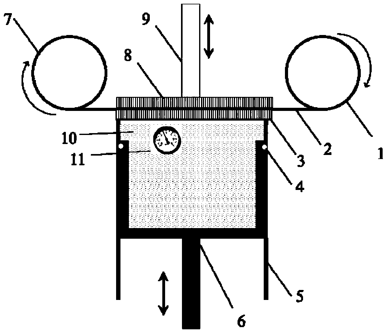
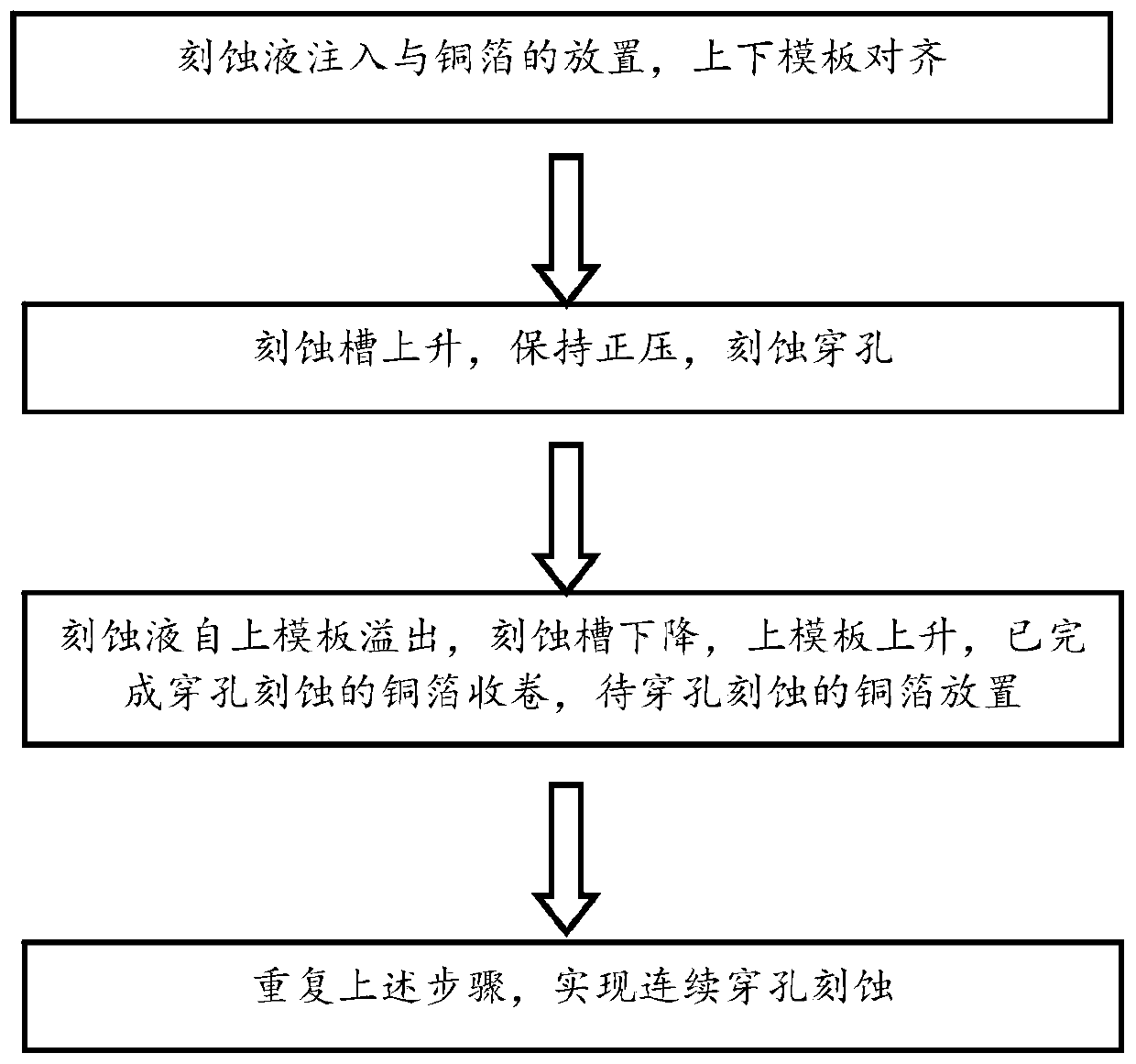
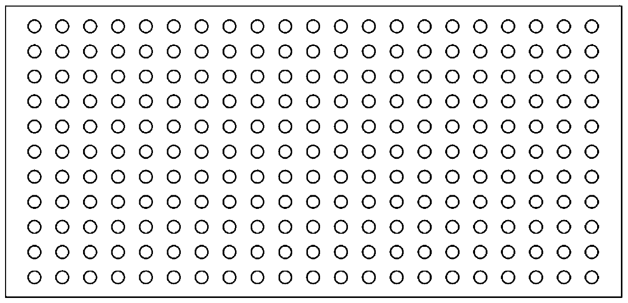

Image

  • A copper foil perforator based on chemical etching and its production process
  • A copper foil perforator based on chemical etching and its production process
  • A copper foil perforator based on chemical etching and its production process

Examples


Embodiment 1

[0029] FeCl with a concentration of 20wt% was injected into the etching groove 3 Etching liquid and make the liquid level exceed the upper edge of the etching tank, place the lower template on the upper edge of the puncher casing, spread the copper foil with a thickness of 6 μm on the upper surface of the lower template, press the upper template on the top of the copper foil, and the upper and lower templates Align the holes in the upper and lower templates with dowels. The upper and lower templates are stainless steel plates with a thickness of 1 mm, and the surface roughness is 1 μm. The template contains circular holes with a diameter of 50 μm. The circular holes are distributed in a rectangular shape, and the distance between the centers of the holes is 80 μm. image 3 shown. Push the etching tank up so that the liquid level of the etching solution rises and contacts the copper foil. The internal pressure of the etching tank is kept at 10Pa. When the etching solution over...

Embodiment 2

[0031] FeCl with a concentration of 20wt% was injected into the etching groove 3 Etching liquid and make the liquid level exceed the upper edge of the etching tank, place the lower template on the upper edge of the piercer casing, spread the copper foil with a thickness of 80 μm on the upper surface of the lower template, press the upper template on the copper foil, and the upper and lower templates Align the holes in the upper and lower templates with dowels. The upper and lower templates are stainless steel plates with a thickness of 5 mm, and the surface roughness is 2 μm. The template contains round holes with a diameter of 1000 μm, which are distributed in a honeycomb shape, and the center spacing of the holes is 1200 μm. Push the etching tank up so that the liquid level of the etching solution rises and contacts the copper foil. The internal pressure of the etching tank is kept at 100 Pa. When the etching solution overflows from the hole of the upper template, lower the ...


PUM

PropertyMeasurementUnit
surface roughnessaaaaaaaaaa
thicknessaaaaaaaaaa
pore sizeaaaaaaaaaa

Abstract

The invention discloses a copper foil perforating machine based on chemical etching. The copper foil perforating machine comprises a copper foil unwinding wheel, a stainless steel lower template, sealing rings, a perforating machine jacket, an etching tank which can be moved up and down, a copper foil winding wheel, a stainless steel upper template, an upper template connecting rod which can be moved up and down, an etching groove internal pressure gage. The invention further provides a production technology for perforated copper foil based on the copper foil perforating machine. The production technology comprises the following step (1) of filling the etching tank with etching liquid, and placing the lower template on the upper edge of the perforating machine jacket; spreading the copperfoil on the lower template flat, and placing the upper template for pressing the copper foil; aligning the upper template to the lower template; the step (2) of pushing the etching tank to rise so that the liquid level rises and is in contact with the copper foil for perforation and etching; and the step (3) of declining the etching tank when the etching liquid overflows from the upper template, and finishing perforation and etching. According to the copper foil perforating machine and the production technology thereof, porous copper foil with high perforation quality and low extent of mechanical damage can be produced, and the quality of finished products is improved; and continuous production is performed so that the production efficiency is improved, and the production process is more environmentally friendly.

Description

Technical field: [0001] The invention relates to a copper foil perforator and its production process, in particular to a chemical etching-based copper foil perforator and its production process. Background technique: [0002] Lithium-ion batteries have the advantages of high unit battery working voltage, long cycle life, and large specific energy. With the continuous development of popular industries such as mobile phone batteries, mobile power supplies, and new energy vehicles, the demand for lithium-ion batteries continues to expand. The requirements for various performance indicators of batteries are also continuously increasing. [0003] At present, the most commonly used anode material substrate for lithium-ion batteries is copper foil. Copper foil is coated with anode materials for battery operation. Problems such as weak adhesion and easy falling off of the surface materials of the anode are often encountered, which affect the working efficiency and use of lithium-ion...

Claims


Application Information

Patent Timeline
Patent Type & Authority Patents(China)
IPC IPC(8): C23F1/02C23F1/18
CPCC23F1/02C23F1/18
Inventor 王宏涛韩屾姚悦程远姜子玮胡春咏刘嘉斌
Owner ZHEJIANG UNIV
Learn More