Supercharge Your Innovation With Domain-Expert AI Agents!

Motor rotor position detection device

A technology for motor rotors and detection devices, applied in circuit devices, using electric/magnetic devices to transmit sensing components, electrical components, etc., can solve problems such as difficulty in structural layout, non-contact power supply methods for modulated rotors, etc., and achieve space The layout is flexible and diverse, the axial structure of the device can be adjusted flexibly, and the effect of axial volume reduction

Active Publication Date: 2019-03-08
TONGJI UNIV
View PDF9 Cites 4 Cited by
  • Summary
  • Abstract
  • Description
  • Claims
  • Application Information

AI Technical Summary

Problems solved by technology

[0007] 3) In special occasions, the structural layout is more difficult
[0014] But this invention does not give how to specifically realize the modulation of the rotor position to WPT and how to realize the non-contact power supply method of the rotor

Method used


Image

  • Motor rotor position detection device
  • Motor rotor position detection device
  • Motor rotor position detection device

Examples


Embodiment 1

[0049] This embodiment focuses on how to realize the modulation effect of the rotor position on the mutual inductance.

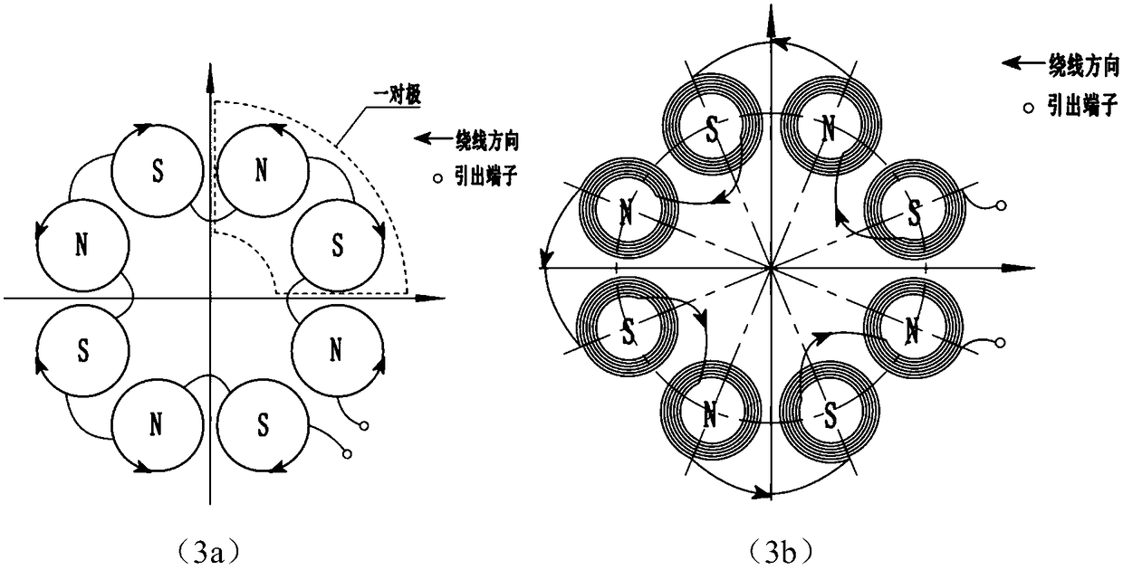
[0050] The device in this embodiment is a rotor position detection device with 4 pairs of poles.

[0051]The primary and secondary windings are composed of an even number of coils with the same structure. Each coil is evenly distributed along the circumference, and its axis is parallel to the axis of the motor. image 3 (3a) is a schematic diagram of the winding structure of the primary and secondary windings of the four-pair pole detection device described above, wherein each coil is circular, and one primary winding is used to establish the excitation magnetic field, one secondary winding, and the primary , The secondary side is coupled by air and there is no iron core, the primary winding is consolidated with the rotor, and the mutual inductance between the primary side and the secondary side changes approximately sinusoidally with the rotor position unde...

Embodiment 2

[0065] This embodiment focuses on how to set up an excitation circuit on the basis of Embodiment 1 to realize the passive design on the rotor side.

[0066] Figure 7 , 8 The implementation methods of the excitation circuit in the case of quadrature double-winding and single-winding are given respectively.

[0067] The field circuit has a field winding and a relay winding, both with compensation circuits. The function of the excitation circuit is to realize the passive design of the primary winding.

[0068] A schematic diagram of the coil structure (of the excitation winding and the relay winding) conforming to the above expression is as follows: Figure 9 express. The excitation winding and the relay winding of the excitation circuit are composed of a circular coil whose axis is the rotation axis of the motor. The mutual inductance between windings is small enough to be ignored.

[0069] Notice, Figure 9 The coil structure can be used not only as a coil placed on the...


PUM


Abstract

The invention relates to a motor rotor position detection device, a primary side winding with a compensation circuit and at least one secondary side winding with a compensation circuit are arranged, the magnetic coupling resonance type wireless electric energy transmission is realized between the primary side winding and the secondary side winding; the primary side winding and the secondary side winding both comprise a coil module, the coil module is formed by connecting an even number of coils with the same structure, the axis of the coil is parallel to the rotating axis of a rotor of a motor, the winding directions of the adjacent coils are opposite to form the staggered n and s magnetic poles, the mutual inductance between the primary side winding and the secondary side winding alternates along with the rotation period of the rotor; the primary side winding is connected with an excitation circuit, the excitation circuit applies alternating current excitation to the primary side winding, and enables the primary side winding to work in a resonance state; and the secondary side winding is connected with an external detection circuit. Compared with the prior art, the device has theadvantages of being flexible and diversified in space arrangement, small in size, high in precision, high in applicability and the like, and the signal input and output based on a stator side can be realized, namely, the rotor is in a passive design.

Description

technical field [0001] The invention belongs to the technical field of position detection and measurement, and relates to a motor rotor position detection device, in particular to a motor rotor position detection device based on the principle of magnetic coupling resonance wireless power transmission. The position detection device can also be used for other non-contact position detection. Background technique [0002] Motor position detection is an important reference for motor control. [0003] In the current motor position detection, the resolver is one of the most important forms, such as figure 1 shown. Taking a common reluctance resolver as an example, generally one primary excitation winding and several (generally two sine and cosine) secondary detection windings are set, and the magnetic permeability between the excitation winding and detection winding changes with the change of the motor rotor , thereby causing a change in the mutual inductance between the two. I...

Claims


Application Information

Patent Timeline
IPC IPC(8): G01D5/14H02J50/12
CPCG01D5/14H02J50/12
Inventor 钟再敏胡程宇
Owner TONGJI UNIV
Features
  • R&D
  • Intellectual Property
  • Life Sciences
  • Materials
  • Tech Scout
  • Unparalleled Data Quality
  • Higher Quality Content
  • 60% Fewer Hallucinations
Learn More