Binocular imaging underwater spectral reflectivity in situ measurement device and method

A technology of spectral reflectance and binocular imaging, which is applied in the field of binocular imaging underwater spectral reflectance in-situ measurement device, can solve the problem of not being able to obtain the surface spectral reflectance data of underwater objects in situ, and the three-dimensional information of the object surface cannot be obtained , spectral information compensation error and other issues, to achieve the effect of ensuring spectral imaging clarity, reducing complexity, jitter and low power consumption

Pending Publication Date: 2019-03-08
ZHEJIANG UNIV
View PDF13 Cites 10 Cited by
  • Summary
  • Abstract
  • Description
  • Claims
  • Application Information

AI Technical Summary

Problems solved by technology

However, due to the process of light transmission in water, the water body (including water, suspended particles in water, dissolved substances in water, etc.) will have serious absorption and scattering attenuation of light, resulting in the overall weakening of light energy and the relative energy of different wavelengths. The distribution changes, therefore, it is necessary to perform water attenuation compensation on the original underwater spectral image to restore the real spectral information of the object surface
U.S. Patent (CN 203444122 U, US Patent 8,767,205) proposes an underwater hyperspectral imaging system, and works in cooperation with an underwater ranging device to compensate for the effect of water body attenuation and obtain underwater spectral image information. However, due to its imaging The method is only for imaging surface detection, and the three-dimensional information of the object surface cannot be obtained, so there is a spectral information compensation error, and the system cannot obtain the spectral reflectance data of the underwater object surface in situ

Method used


Image

  • Binocular imaging underwater spectral reflectivity in situ measurement device and method
  • Binocular imaging underwater spectral reflectivity in situ measurement device and method
  • Binocular imaging underwater spectral reflectivity in situ measurement device and method

Examples


Embodiment Construction

[0036] The present invention will be described in further detail below in conjunction with the accompanying drawings and specific embodiments.

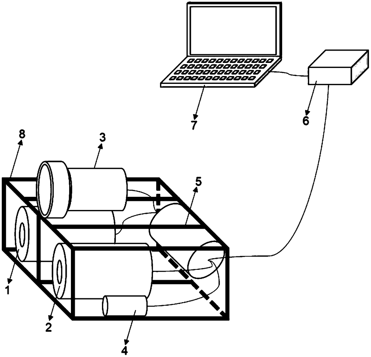
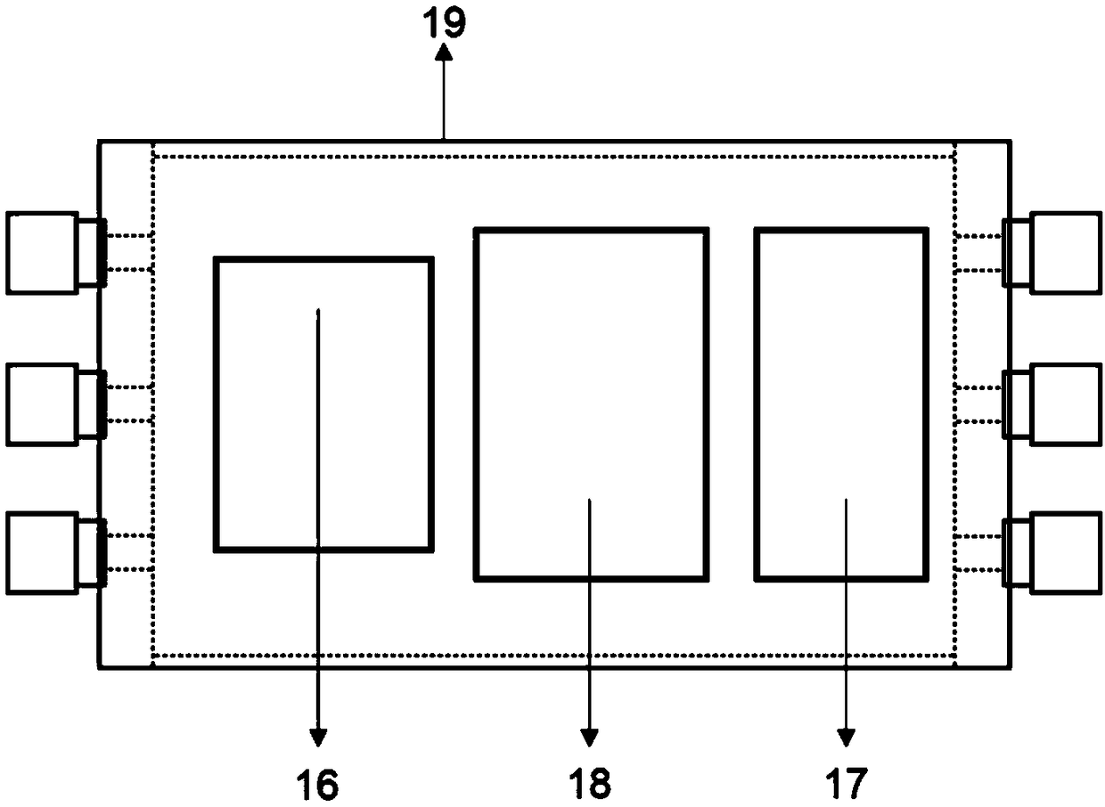
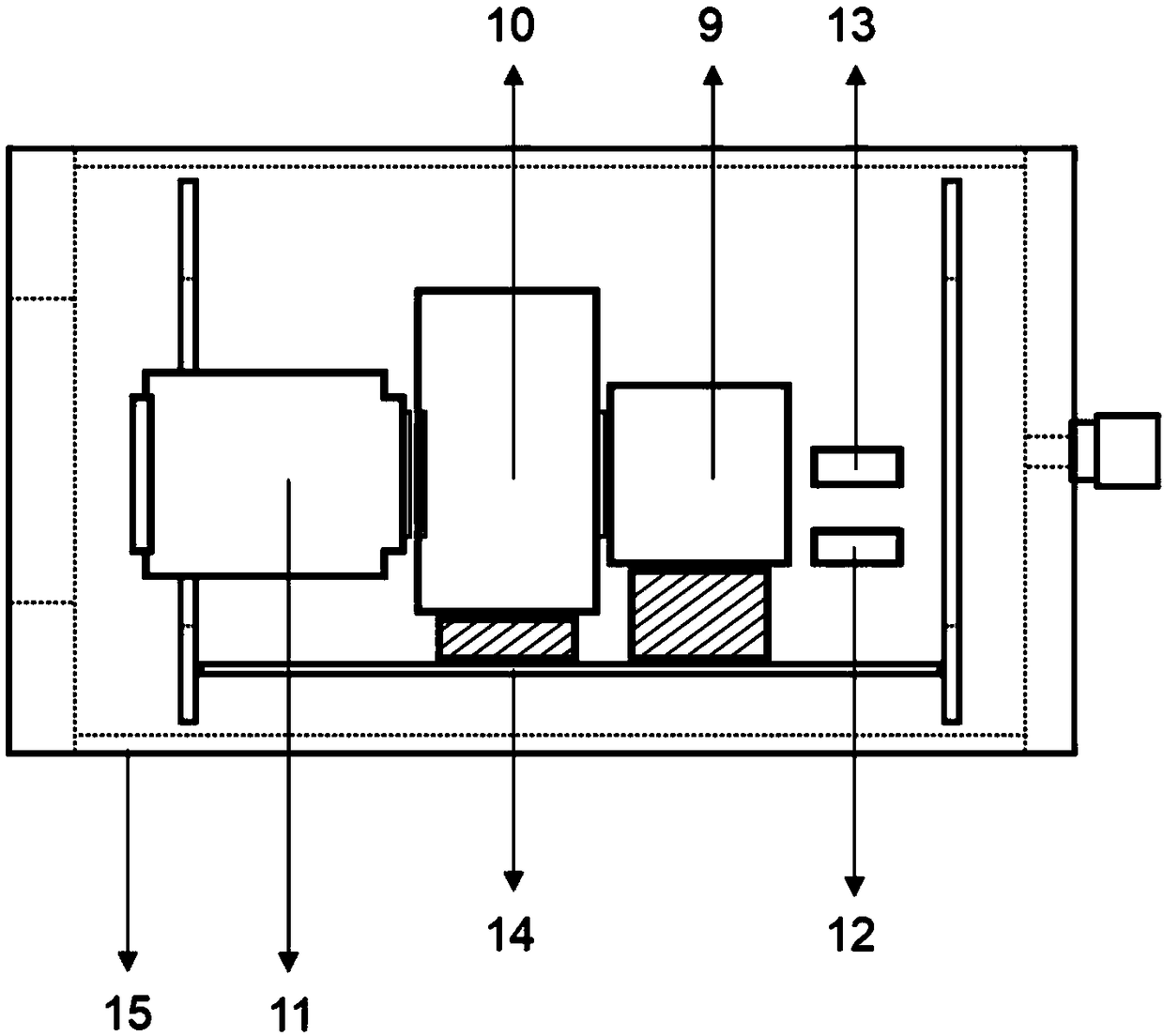
[0037] Such as Figure 1-5 As shown, a binocular imaging underwater spectral reflectance in-situ measuring device of the present invention includes a binocular spectral imaging subsystem, an underwater wide-spectrum LED light source 3, a water body attenuation coefficient measuring instrument 4, a control unit 5, and an optical transceiver at the receiving end 6. Host computer 7, bracket 8; wherein, the control unit includes a control unit sealed cabin 19 and a sending end optical transceiver 16 installed in the control unit sealed cabin 19, a power management module 17 and a micro industrial computer 18; the power management Module 17 provides working voltage for the entire measuring device; the control unit airtight compartment 19 is composed of a metal cylinder, front end cover, rear end cover, etc., and is statically sealed throug...


PUM


Abstract

The invention discloses a binocular imaging underwater spectral reflectivity in situ measurement device and method. The binocular imaging underwater spectral reflectivity in situ measurement device comprises a binocular spectral imaging subsystem, an underwater broadband-spectrum LED (light emitting diode) light source, a water attenuation coefficient measurement instrument, a control unit, a receiving side optical transceiver, an upper computer and a support, wherein the binocular spectral imaging subsystem is composed of a first underwater spectral imaging instrument and a second underwaterspectral imaging instrument, which are completely identical in parameters and synchronously collect an underwater target spectral image sequence; the water attenuation coefficient measurement instrument is fixed onto the support for measuring the optical attenuation coefficient of waters; the first underwater spectral imaging instrument, the second underwater spectral imaging instrument, the underwater broadband-spectrum LED light source and the water attenuation coefficient measurement instrument are connected with the control unit, the control unit is connected with the receiving side optical transceiver, and the receiving side optical transceiver is connected with the upper computer. The binocular imaging underwater spectral reflectivity in situ measurement device can achieve in situ, quantitative and accurate measurement of the surface spectral reflectivity of an underwater target.

Description

technical field [0001] The invention relates to an underwater spectral reflectance measurement device, in particular to a binocular imaging type underwater spectral reflectance in-situ measurement device and a measurement method. Background technique [0002] The spectral reflectance of the surface of an object is the ratio between the spectral radiant energy reflected by the surface of the object and the spectral radiant energy incident on the surface of the object. The characteristic of object spectral reflectance has been widely used in satellite remote sensing, agriculture, food, biomedicine, military and other fields, but related research and applications are mainly concentrated on land and sea, while underwater research and applications are relatively less. [0003] With the continuous deepening of human research on the ocean, people's requirements for underwater environment monitoring and detection are also increasing. Researchers from all over the world are actively...

Claims


Application Information

Patent Timeline
Patent Type & Authority Applications(China)
IPC IPC(8): G01N21/27G01V8/10
CPCG01N21/27G01V8/10
Inventor 宋宏吴超鹏申屠溢醇王文鑫万启新杨萍方美芬
Owner ZHEJIANG UNIV
Why Eureka
Try Eureka